DEMO9S08DZ60 Freescale Semiconductor, DEMO9S08DZ60 Datasheet - Page 13
DEMO9S08DZ60
Manufacturer Part Number
DEMO9S08DZ60
Description
BOARD DEMO
Manufacturer
Freescale Semiconductor
Type
MCUr
Datasheets
1.DEMO9S08DZ60.pdf
(416 pages)
2.DEMO9S08DZ60.pdf
(1 pages)
3.DEMO9S08DZ60.pdf
(16 pages)
4.DEMO9S08DZ60.pdf
(2 pages)
5.DEMO9S08DZ60.pdf
(1 pages)
Specifications of DEMO9S08DZ60
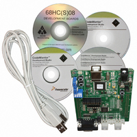
Contents
Board, Cable, CD
Processor To Be Evaluated
MC9S08DZ60
Interface Type
RS-232, USB
Silicon Manufacturer
Freescale
Core Architecture
HCS08
Core Sub-architecture
HCS08
Silicon Core Number
MC9S08
Silicon Family Name
S08D
Kit Contents
MC9S08DZ60 Board, Software, Cables, Connectors
Rohs Compliant
Yes
For Use With/related Products
MC9S08DZ60
Lead Free Status / RoHS Status
Lead free / RoHS Compliant


D E M O 9 S 0 8 D Z 6 0
CAN Communications
The DEMO9S08DZ60 provides a high-speed CAN physical layer interface (PHY). A 3-pin
connector provides connectivity to the off-board CAN bus. The CAN PHY connects to the
CAN0 channel on the MCU. The PHY supports data rates up to 1 MBPS with edge-rate
control to reduce EMI/RFI. The figure below shows the pin-out of the CAN_PORT connector.
Figure 8: CAN_PORT Connector
CAN Termination
The DEMO9S08DZ60 applies a 121 ohm differential termination to the CAN bus. An option
jumper allows the user to selectively apply termination. Installing the CTE option jumper
applies termination to the differential CAN bus. Removing the CTE option jumper removes the
CAN termination.
Figure 9: CTE Option Header
VRH/VRL
MCU inputs VRH and VRL provide the upper and lower voltage reference for the analog to
digital (ATD) converter. By default, VRH is tied to VDD and VRL is tied to ground. Adequate
filtering has been added to provide a voltage reference with minimal ripple. Either, or both,
references may be isolated to provide alternate ATD input references. A test point via on each
signal, labeled VRH, or VRL, provides a convenient attach point.
A 0-ohm configuration resistor allows isolation of each reference voltage. Removing R25
isolates VRH while removing R26 isolates VRL. Install 0805 sized 0-ohm resistors in these
locations to restore the board to default configuration.
Care must be exercised when using alternate input references.
resistor must be removed before applying an alternate voltage reference or the board may be
damaged. The table below summarizes the changes necessary to use alternate VRH and/or
VRL.
CTE
1
1
2
3
2
CAN_H
GND
CAN_L
Enabled
ON
Disabled
OFF
The CAN PHY connects to the CAN0
channel in the MCU
13
The associated isolation
D E C E M B E R
2 ,
2 0 0 6
Related parts for DEMO9S08DZ60
Image
Part Number
Description
Manufacturer
Datasheet
Request
R

Part Number:
Description:
Manufacturer:
Freescale Semiconductor, Inc
Datasheet:
Part Number:
Description:
Manufacturer:
Freescale Semiconductor, Inc
Datasheet:
Part Number:
Description:
Manufacturer:
Freescale Semiconductor, Inc
Datasheet:
Part Number:
Description:
Manufacturer:
Freescale Semiconductor, Inc
Datasheet:
Part Number:
Description:
Manufacturer:
Freescale Semiconductor, Inc
Datasheet:
Part Number:
Description:
Manufacturer:
Freescale Semiconductor, Inc
Datasheet:
Part Number:
Description:
Manufacturer:
Freescale Semiconductor, Inc
Datasheet:
Part Number:
Description:
Manufacturer:
Freescale Semiconductor, Inc
Datasheet:
Part Number:
Description:
Manufacturer:
Freescale Semiconductor, Inc
Datasheet:
Part Number:
Description:
Manufacturer:
Freescale Semiconductor, Inc
Datasheet:
Part Number:
Description:
Manufacturer:
Freescale Semiconductor, Inc
Datasheet:
Part Number:
Description:
Manufacturer:
Freescale Semiconductor, Inc
Datasheet:
Part Number:
Description:
Manufacturer:
Freescale Semiconductor, Inc
Datasheet:
Part Number:
Description:
Manufacturer:
Freescale Semiconductor, Inc
Datasheet:
Part Number:
Description:
Manufacturer:
Freescale Semiconductor, Inc
Datasheet: