DK-CYCII-2C20N Altera, DK-CYCII-2C20N Datasheet - Page 43
DK-CYCII-2C20N
Manufacturer Part Number
DK-CYCII-2C20N
Description
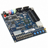
CYCLONE II STARTER KIT EP2C20N
Manufacturer
Altera
Series
Cyclone® IIr
Type
FPGAr
Specifications of DK-CYCII-2C20N
Contents
Dev Board, Quartus®II Web Edition, Nios®II Web Edition, Cables, Accessories, Reference Designs and Demos
Silicon Manufacturer
Altera
Core Architecture
FPGA
Core Sub-architecture
Cyclone
Silicon Core Number
EP2C
Silicon Family Name
Cyclone II
Rohs Compliant
Yes
For Use With/related Products
Cyclone®II FPGAs
Lead Free Status / RoHS Status
Lead free / RoHS Compliant
Other names
544-1736
Available stocks
Company
Part Number
Manufacturer
Quantity
Price
Company:

Part Number:
DK-CYCII-2C20N
Manufacturer:
Altera
Quantity:
135


Factory
Configuration
Altera Corporation
October 2006
This chapter provides a number of examples of advanced circuits
implemented on the development board. These circuits provide
demonstrations of the major features on the board, such as its audio and
video capabilities. For each demonstration, the kit includes the Cyclone II
FPGA (or EPCS4 serial EEPROM) configuration file, as well as the full
source code in Verilog HDL code.
All of the associated files reside in the <kit path>\Examples directory
after installation. The section describing each demonstration provides the
location for the example files.
The development board is shipped from the factory with a default
configuration that demonstrates some of the basic features of the board.
File Locations
■
■
Demonstration Setup
To set up the demonstration, perform the following steps:
1.
2.
3.
4.
Project directory: CII_Starter_Default
Bit stream used: CII_Starter_Default.sof or CII_Starter_Default.pof
Power up the development board with the USB cable connected to
the USB-Blaster port. If necessary (that is, if the default factory
configuration of the development board is not currently stored in
EPCS4 device), download the bit stream to the board by using either
JTAG or AS programming
Observe that the 7-segment displays display a sequence of
characters and that the red and green LEDs flash.
Optionally, connect a VGA display to the VGA D-SUB connector.
When connected, the VGA display should show a pattern of colors.
Optionally, connect a powered speaker to the stereo audio-out jack.
6. Advanced Examples
6–1
Related parts for DK-CYCII-2C20N
Image
Part Number
Description
Manufacturer
Datasheet
Request
R


Part Number:
Description:
CPLD, EP610 Family, ECMOS Process, 300 Gates, 16 Macro Cells, 16 Reg., 16 User I/Os, 5V Supply, 35 Speed Grade, 24DIP
Manufacturer:
Altera Corporation
Datasheet:
Part Number:
Description:
CPLD, EP610 Family, ECMOS Process, 300 Gates, 16 Macro Cells, 16 Reg., 16 User I/Os, 5V Supply, 15 Speed Grade, 24DIP
Manufacturer:
Altera Corporation
Datasheet:
Part Number:
Description:
Manufacturer:
Altera Corporation
Datasheet:
Part Number:
Description:
CPLD, EP610 Family, ECMOS Process, 300 Gates, 16 Macro Cells, 16 Reg., 16 User I/Os, 5V Supply, 30 Speed Grade, 24DIP
Manufacturer:
Altera Corporation
Datasheet:
Part Number:
Description:
High-performance, low-power erasable programmable logic devices with 8 macrocells, 10ns
Manufacturer:
Altera Corporation
Datasheet:
Part Number:
Description:
High-performance, low-power erasable programmable logic devices with 8 macrocells, 7ns
Manufacturer:
Altera Corporation
Datasheet:
Part Number:
Description:
Classic EPLD
Manufacturer:
Altera Corporation
Datasheet:
Part Number:
Description:
High-performance, low-power erasable programmable logic devices with 8 macrocells, 10ns
Manufacturer:
Altera Corporation
Datasheet:
Part Number:
Description:
Manufacturer:
Altera Corporation
Datasheet:
Part Number:
Description:
Manufacturer:
Altera Corporation
Datasheet:
Part Number:
Description:
Manufacturer:
Altera Corporation
Datasheet:
Part Number:
Description:
CPLD, EP610 Family, ECMOS Process, 300 Gates, 16 Macro Cells, 16 Reg., 16 User I/Os, 5V Supply, 25 Speed Grade, 24DIP
Manufacturer:
Altera Corporation
Datasheet:
Part Number:
Description:
Manufacturer:
Altera Corporation
Datasheet: