ATAVRTS2080B Atmel, ATAVRTS2080B Datasheet - Page 173
ATAVRTS2080B
Manufacturer Part Number
ATAVRTS2080B
Description
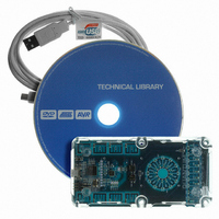
BOARD EVAL FOR ATTINY88 LIBRARY
Manufacturer
Atmel
Series
QTouch™r
Specifications of ATAVRTS2080B
Sensor Type
Touch, Capacitive
Sensing Range
1 Rotor, 1 Slider, and 2 Buttons/Keys
Interface
Application Programming Interface (API)
Voltage - Supply
1.8 V ~ 5.5 V
Embedded
Yes, MCU, 8-Bit
Utilized Ic / Part
ATtiny88
Tool Type
Development Kit
Cpu Core
AVR 8 / 32
Data Bus Width
8 bit
Core Architecture
AVR
Silicon Manufacturer
Atmel
Silicon Core Number
ATtiny88
Silicon Family Name
AVR
Kit Contents
Board CD Docs
Development Tool Type
Hardware / Software - Eval/Demo Board
Rohs Compliant
Yes
Lead Free Status / RoHS Status
Lead free / RoHS Compliant
Sensitivity
-
Lead Free Status / Rohs Status
Details
Other names
Q4359953


7.5.2.1.2
When SNS and SNSK pins are connected to the same port, the even pin numbers will be used as
SNS pins and the odd pins will be used as the SNSK pins.
7.5.2.2
The libraries internally need SNS_array and SNSK_array masks. These masks need to be
defined under Macro QTOUCH_STUDIO_MASKS as per the following rules given below:
1.
Channel0 and Channel2.And SNS_array[1] and SNSK_array[1] mask is used for configuring the
Channel1 and Channel3.And In case of Intraport SNS_array[0] and SNSK-array[0] are used for
all the four channels configured based on enabled bits in SNS_array[0] and SNSK-array[0].
2. The channel numbers are allocated based on enabled SNS pins starting from LSBBit.
In case of Interport, Keys on adjacent channels should be placed on different masks. Channel0
and Channel1 should be on different SNS/SNSK masks ie channel0 on
SNS_array[0]/SNSK_array[0] and channel1 on SNS_array[1]/ SNSK_array[1].
But in case of Intraport, Keys on adjacent channels should be placed on same masks. Channel0
and Channel2 should be on same mask ie SNS_array[0]/SNSK_array[0] and Channel1 and
Channel3 on SNS_array[1]/ SNSK_array[1].
7.5.2.2.1
1. Enable the Bit0 in SNS_array[0] and Bit0 in SNSK_array[0] mask when enabling Channel0.
2. Enable the Bit1 in SNS_array[1] and Bit1 in SNSK_array[1] mask when enabling Channel1.
3. Enable the Bit2 in SNS_array[0] and Bit2 in SNSK_array[0] mask when enabling Channel2.
4. Enable the Bit3 in SNS_array[1] and Bit3 in SNSK_array[1] mask when enabling Channel3.
Example 1:
In a 4 channel library, two keys on channel 0 and 3 are enabled.SNS on Port A and SNSK on
Port B .Channel0 will A0B0 and Channel3 will be A3B3.
The SNS and SNSK masks will be
SNS_array[0]=0x01;
SNS_array[1]=0x08;
SNSK_array[0]=0x01;
SNSK_array[1]=0x08;
•
•
•
The number of channels supported will be limited 4 channels
For e.g., for a 4 channel configuration where the SNS and SNSK pins are connected to
Port B, the port pins 0&1 are used for channel 0.
The channel number is derived from the position of the pins used for SNS and SNSK
lines for any channel.
o
In case of Interport, SNS_array[0] and SNSK_array[0] mask is used for configuring the
Rules For Configuring SNS and SNSK masks for 2K Devices
Configuring SNS and SNSK masks in case of Interport:
Channel numbering when routing SNS and SNSK pins to the same port
For e.g., pins 4 and 5 are connected to a SNS/SNSK pair and the channel number
associated with the SNS/SNSK pin is 2.
channel number = floor( [SNS(or SNSK) pin number] / 2 )
173
Related parts for ATAVRTS2080B
Image
Part Number
Description
Manufacturer
Datasheet
Request
R


Part Number:
Description:
DEV KIT FOR AVR/AVR32
Manufacturer:
Atmel
Datasheet:

Part Number:
Description:
INTERVAL AND WIPE/WASH WIPER CONTROL IC WITH DELAY
Manufacturer:
ATMEL Corporation
Datasheet:
Part Number:
Description:
Low-Voltage Voice-Switched IC for Hands-Free Operation
Manufacturer:
ATMEL Corporation
Datasheet:
Part Number:
Description:
MONOLITHIC INTEGRATED FEATUREPHONE CIRCUIT
Manufacturer:
ATMEL Corporation
Datasheet:
Part Number:
Description:
AM-FM Receiver IC U4255BM-M
Manufacturer:
ATMEL Corporation
Datasheet:
Part Number:
Description:
Monolithic Integrated Feature Phone Circuit
Manufacturer:
ATMEL Corporation
Datasheet:
Part Number:
Description:
Multistandard Video-IF and Quasi Parallel Sound Processing
Manufacturer:
ATMEL Corporation
Datasheet:
Part Number:
Description:
High-performance EE PLD
Manufacturer:
ATMEL Corporation
Datasheet:
Part Number:
Description:
8-bit Flash Microcontroller
Manufacturer:
ATMEL Corporation
Datasheet:
Part Number:
Description:
2-Wire Serial EEPROM
Manufacturer:
ATMEL Corporation
Datasheet: