ATAVRTS2080B Atmel, ATAVRTS2080B Datasheet - Page 112
ATAVRTS2080B
Manufacturer Part Number
ATAVRTS2080B
Description
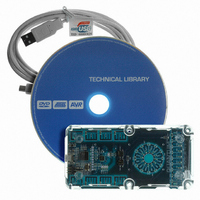
BOARD EVAL FOR ATTINY88 LIBRARY
Manufacturer
Atmel
Series
QTouch™r
Specifications of ATAVRTS2080B
Sensor Type
Touch, Capacitive
Sensing Range
1 Rotor, 1 Slider, and 2 Buttons/Keys
Interface
Application Programming Interface (API)
Voltage - Supply
1.8 V ~ 5.5 V
Embedded
Yes, MCU, 8-Bit
Utilized Ic / Part
ATtiny88
Tool Type
Development Kit
Cpu Core
AVR 8 / 32
Data Bus Width
8 bit
Core Architecture
AVR
Silicon Manufacturer
Atmel
Silicon Core Number
ATtiny88
Silicon Family Name
AVR
Kit Contents
Board CD Docs
Development Tool Type
Hardware / Software - Eval/Demo Board
Rohs Compliant
Yes
Lead Free Status / RoHS Status
Lead free / RoHS Compliant
Sensitivity
-
Lead Free Status / Rohs Status
Details
Other names
Q4359953


6.3.7.2.2
When the External Discharge arrangement is used, a logic-level (DIS) pin is connected to an
external resistor (Rdis) that can be used to control the discharge of the Capacitors. A typical
value for Rdis is 100 kOhm. This value of Rdis will give a discharge current of approximately
1.1V/(100 kOhm) = 11 microAmp. The case C shows this arrangement. The Resistive drive
option on the X and Yk lines can be optionally enabled or disabled with this arrangement. When
the Resistive drive is option is not enabled, it is recommended to use 1kOhm resistors on X and
Yk Lines external to the UC3L device.
6.3.7.2.3
When the SMP Discharge mode arrangement is used, a logic-level (SMP) pin is connected to the
capacitors through external high value resistors for the discharge of the capacitors. The case D
shows this arrangement. The Resistive drive option on the X and Yk lines can be optionally
enabled or disabled with this arrangement. When the Resistive drive is option is not enabled, it is
recommended to use 1kOhm resistors on X and Yk Lines external to the UC3L device.
6.3.7.2.4
The VDIV pin provides an option to make ACREFN a small positive voltage if required. The VDIV
pin is driven when the analog comparators are in use, and this signal can be used along with a
voltage divider arrangement to create a small positive offset on the ACREFN pin. The VDIVEN
option can be used optionally with any of the QMatrix modes discussed in the previous sections.
Typical values for Ra and Rb are Ra=16500 ohm and Rb = 50 ohm. Assuming a 3.3V I/O supply,
this will shift the comparator threshold by 3.3V*(Rb/(Ra+Rb)) which is 10 mV. The VDIVEN pin
option usage in the Internal Discharge mode scenario is shown in case E.
6.3.7.2.5
In order to prevent interference from the 50 or 60 Hz mains line the CAT can optionally trigger
QMatrix acquisition on the external SYNC input signal. The SYNC signal should be derived from
the mains line and the acquisition will trigger on a falling edge of this signal. The SYNC pin
option can be used with any of the QMatrix modes discussed in the previous sections. The
SYNC pin usage in the Internal Discharge mode scenario is shown in case F.
For QMatrix method SMP, DIS, VDIV and SYNC pin options discussed in this Section, Refer to
Section
112
6.3.15.2.13.
SMP Discharge Mode
VDIVEN Voltage Divider Enable option
External Discharge mode
SYNC pin option
8207J-AT42-02/11
Related parts for ATAVRTS2080B
Image
Part Number
Description
Manufacturer
Datasheet
Request
R


Part Number:
Description:
DEV KIT FOR AVR/AVR32
Manufacturer:
Atmel
Datasheet:

Part Number:
Description:
INTERVAL AND WIPE/WASH WIPER CONTROL IC WITH DELAY
Manufacturer:
ATMEL Corporation
Datasheet:
Part Number:
Description:
Low-Voltage Voice-Switched IC for Hands-Free Operation
Manufacturer:
ATMEL Corporation
Datasheet:
Part Number:
Description:
MONOLITHIC INTEGRATED FEATUREPHONE CIRCUIT
Manufacturer:
ATMEL Corporation
Datasheet:
Part Number:
Description:
AM-FM Receiver IC U4255BM-M
Manufacturer:
ATMEL Corporation
Datasheet:
Part Number:
Description:
Monolithic Integrated Feature Phone Circuit
Manufacturer:
ATMEL Corporation
Datasheet:
Part Number:
Description:
Multistandard Video-IF and Quasi Parallel Sound Processing
Manufacturer:
ATMEL Corporation
Datasheet:
Part Number:
Description:
High-performance EE PLD
Manufacturer:
ATMEL Corporation
Datasheet:
Part Number:
Description:
8-bit Flash Microcontroller
Manufacturer:
ATMEL Corporation
Datasheet:
Part Number:
Description:
2-Wire Serial EEPROM
Manufacturer:
ATMEL Corporation
Datasheet: