ATAVRTS2080B Atmel, ATAVRTS2080B Datasheet - Page 117
ATAVRTS2080B
Manufacturer Part Number
ATAVRTS2080B
Description
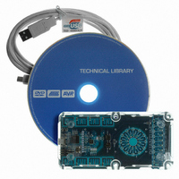
BOARD EVAL FOR ATTINY88 LIBRARY
Manufacturer
Atmel
Series
QTouch™r
Specifications of ATAVRTS2080B
Sensor Type
Touch, Capacitive
Sensing Range
1 Rotor, 1 Slider, and 2 Buttons/Keys
Interface
Application Programming Interface (API)
Voltage - Supply
1.8 V ~ 5.5 V
Embedded
Yes, MCU, 8-Bit
Utilized Ic / Part
ATtiny88
Tool Type
Development Kit
Cpu Core
AVR 8 / 32
Data Bus Width
8 bit
Core Architecture
AVR
Silicon Manufacturer
Atmel
Silicon Core Number
ATtiny88
Silicon Family Name
AVR
Kit Contents
Board CD Docs
Development Tool Type
Hardware / Software - Eval/Demo Board
Rohs Compliant
Yes
Lead Free Status / RoHS Status
Lead free / RoHS Compliant
Sensitivity
-
Lead Free Status / Rohs Status
Details
Other names
Q4359953


6.3.7.6
The touch_qm_channel_update_burstlen API can be used for Disabling and Re-enabling of
QMatrix Sensors. In order to Disable a sensor, the QMatrix burst length value of all the Touch
Channels corresponding to the Sensor must be set to 1. For Example, when a Wheel or Slider is
composed of 4 Touch Channels, the touch_qm_channel_update_burstlen API should be used to
set the burst length of all the 4 Touch Channels to 1.
touch_qm_channel_update_burstlen API should be used to set burst length of the corresponding
single Touch Channel of the Button to 1. Similarly, when re-enabling a Sensor, appropriate burst
length must be set to all the Touch channels corresponding to the Sensor.
When a QMatrix Sensor is Disabled or re-enabled, it is mandatory to force Calibration on all
Sensors. The Calibration of all Sensors is done using the touch_qm_sensors_calibrate API.
Note: When disabling a Wheel or Slider, care must be taken to set the burst length of all the
Touch channels corresponding to the Wheel or Slider to 1. If any of the Touch channels are
missed out, it may result in undesired behavior of the Wheel or Slider. Similarly when re-enabling
a Wheel or Slider, burst length of all the Touch channels corresponding to the Wheel or Slider
must be set to an appropriate value. If any of the Touch Channels are left disabled with a burst
length value 1, it may result in undesired behavior of Wheel or Slider.
6.3.8
6.3.8.1
Please refer AT32UC3L datasheet Table 28-2 Pin Selection Guide and Table 3-1 GPIO
Controller Function multiplexing, for mapping between the QTouch method pin name
(SNS/SNSK) and the GPIO pin. The CAT module provides an option to enable a nominal output
resistance of 1kOhm on specific CAT module pins during the burst phase. The Table below
captures the different QTouch method pin wherein a Resistive Drive can be optionally enabled.
The rows marked with Grey indicate that Resistive Drive option is not available on that pin. By
carefully choosing the QTouch method SNSK pins wherein Resistive Drive can be enabled,
saving on external components is possible.
and Touch channels required for different QTouch method sensor. Also,
the various Pin Configuration options for the QTouch Library that can be used to specify a user
defined configuration.
QTouch Group A/B method sensor operation for UC3L
QMatrix method Disable and Re-enable Sensor for UC3L
QTouch Group A/B method pin selection for UC3L
Section 6.3.1.2
provides detail on the number of Pin
For the case of a Button,
Section 6.3.11
indicates
117
Related parts for ATAVRTS2080B
Image
Part Number
Description
Manufacturer
Datasheet
Request
R


Part Number:
Description:
DEV KIT FOR AVR/AVR32
Manufacturer:
Atmel
Datasheet:

Part Number:
Description:
INTERVAL AND WIPE/WASH WIPER CONTROL IC WITH DELAY
Manufacturer:
ATMEL Corporation
Datasheet:
Part Number:
Description:
Low-Voltage Voice-Switched IC for Hands-Free Operation
Manufacturer:
ATMEL Corporation
Datasheet:
Part Number:
Description:
MONOLITHIC INTEGRATED FEATUREPHONE CIRCUIT
Manufacturer:
ATMEL Corporation
Datasheet:
Part Number:
Description:
AM-FM Receiver IC U4255BM-M
Manufacturer:
ATMEL Corporation
Datasheet:
Part Number:
Description:
Monolithic Integrated Feature Phone Circuit
Manufacturer:
ATMEL Corporation
Datasheet:
Part Number:
Description:
Multistandard Video-IF and Quasi Parallel Sound Processing
Manufacturer:
ATMEL Corporation
Datasheet:
Part Number:
Description:
High-performance EE PLD
Manufacturer:
ATMEL Corporation
Datasheet:
Part Number:
Description:
8-bit Flash Microcontroller
Manufacturer:
ATMEL Corporation
Datasheet:
Part Number:
Description:
2-Wire Serial EEPROM
Manufacturer:
ATMEL Corporation
Datasheet: