STEVAL-ISQ002V1 STMicroelectronics, STEVAL-ISQ002V1 Datasheet - Page 94
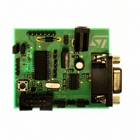
STEVAL-ISQ002V1
Manufacturer Part Number
STEVAL-ISQ002V1
Description
BOARD EVAL BASED ON ST72264G1
Manufacturer
STMicroelectronics
Specifications of STEVAL-ISQ002V1
Main Purpose
Interface, PMBus
Embedded
Yes, MCU, 8-Bit
Utilized Ic / Part
ST72F264
Primary Attributes
The PMBus™ Interface Using the ST7 I2C Peripheral
Secondary Attributes
Firmware in C Language
Product
Power Management Modules
Lead Free Status / RoHS Status
Lead free / RoHS Compliant
Other names
497-6423
Available stocks
Company
Part Number
Manufacturer
Quantity
Price
Company:

Part Number:
STEVAL-ISQ002V1
Manufacturer:
STMicroelectronics
Quantity:
1


ST72260Gx, ST72262Gx, ST72264Gx
SERIAL COMMUNICATIONS INTERFACE (Cont’d)
11.5.4.7 Parity Control
Parity control (generation of parity bit in transmis-
sion and parity checking in reception) can be ena-
bled by setting the PCE bit in the SCICR1 register.
Depending on the frame length defined by the M
bit, the possible SCI frame formats are as listed in
Table
Table 18. Frame Formats
Legend: SB = Start Bit, STB = Stop Bit,
PB = Parity Bit
Note: In case of wake up by an address mark, the
MSB bit of the data is taken into account and not
the parity bit
Even parity: the parity bit is calculated to obtain
an even number of “1s” inside the frame made of
the 7 or 8 LSB bits (depending on whether M is
equal to 0 or 1) and the parity bit.
Ex: data=00110101; 4 bits set => parity bit will be
0 if even parity is selected (PS bit = 0).
Odd parity: the parity bit is calculated to obtain an
odd number of “1s” inside the frame made of the 7
or 8 LSB bits (depending on whether M is equal to
0 or 1) and the parity bit.
Ex: data=00110101; 4 bits set => parity bit will be
1 if odd parity is selected (PS bit = 1).
Transmission mode: If the PCE bit is set then the
MSB bit of the data written in the data register is
not transmitted but is changed by the parity bit.
Reception mode: If the PCE bit is set then the in-
terface checks if the received data byte has an
94/172
M bit
0
0
1
1
18.
PCE bit
1
0
0
1
| SB | 7-bit data | PB | STB |
| SB | 8-bit data PB | STB |
| SB | 9-bit data | STB |
| SB | 8 bit data | STB |
SCI frame
even number of “1s” if even parity is selected
(PS=0) or an odd number of “1s” if odd parity is se-
lected (PS=1). If the parity check fails, the PE flag
is set in the SCISR register and an interrupt is gen-
erated if PIE is set in the SCICR1 register.
11.5.4.8 SCI Clock Tolerance
During reception, each bit is sampled 16 times.
The majority of the 8th, 9th and 10th samples is
considered as the bit value. For a valid bit detec-
tion, all the three samples should have the same
value otherwise the noise flag (NF) is set. For ex-
ample: if the 8th, 9th and 10th samples are 0, 1
and 1 respectively, then the bit value will be “1”,
but the Noise Flag bit is be set because the three
samples values are not the same.
Consequently, the bit length must be long enough
so that the 8th, 9th and 10th samples have the de-
sired bit value. This means the clock frequency
should not vary more than 6/16 (37.5%) within one
bit. The sampling clock is resynchronized at each
start bit, so that when receiving 10 bits (one start
bit, 1 data byte, 1 stop bit), the clock deviation
must not exceed 3.75%.
Note: The internal sampling clock of the microcon-
troller samples the pin value on every falling edge.
Therefore, the internal sampling clock and the time
the application expects the sampling to take place
may be out of sync. For example: If the baud rate
is 15.625 kbaud (bit length is 64µs), then the 8th,
9th and 10th samples will be at 28µs, 32µs & 36µs
respectively (the first sample starting ideally at
0µs). But if the falling edge of the internal clock oc-
curs just before the pin value changes, the sam-
ples would then be out of sync by ~4us. This
means the entire bit length must be at least 40µs
(36µs for the 10th sample + 4µs for synchroniza-
tion with the internal sampling clock).
Related parts for STEVAL-ISQ002V1
Image
Part Number
Description
Manufacturer
Datasheet
Request
R

Part Number:
Description:
BOARD RGB CTR ST7,STP08C596MTR
Manufacturer:
STMicroelectronics
Datasheet:

Part Number:
Description:
Power Management IC Development Tools Full Speed USB to RS232 Bridge Demo
Manufacturer:
STMicroelectronics
Datasheet:
Part Number:
Description:
Power Management IC Development Tools 2.5W solar eval BRD USB SPV1040 LD39050
Manufacturer:
STMicroelectronics
Datasheet:

Part Number:
Description:
BOARD EVAL FOR MEMS SENSORS
Manufacturer:
STMicroelectronics
Datasheet:

Part Number:
Description:
KIT DEV STARTER ST10F276Z5
Manufacturer:
STMicroelectronics
Datasheet:

Part Number:
Description:
BOARD EVAL HDMI $ VIDEO SWITCH
Manufacturer:
STMicroelectronics
Datasheet:

Part Number:
Description:
BOARD DEMO ACCELEROMETER DIL24
Manufacturer:
STMicroelectronics
Datasheet:

Part Number:
Description:
BOARD STLM75/STDS75/ST72F651
Manufacturer:
STMicroelectronics
Datasheet:

Part Number:
Description:
EVAL BOARD 3AXIS MEMS ACCELLRMTR
Manufacturer:
STMicroelectronics
Datasheet:

Part Number:
Description:
BOARD EVAL 8BIT MICRO + TDE1708
Manufacturer:
STMicroelectronics
Datasheet:
Part Number:
Description:
STMicroelectronics [RIPPLE-CARRY BINARY COUNTER/DIVIDERS]
Manufacturer:
STMicroelectronics
Datasheet:
Part Number:
Description:
STMicroelectronics [LIQUID-CRYSTAL DISPLAY DRIVERS]
Manufacturer:
STMicroelectronics
Datasheet:
Part Number:
Description:
BOARD EVAL FOR MEMS SENSORS
Manufacturer:
STMicroelectronics
Datasheet: