STEVAL-ISQ002V1 STMicroelectronics, STEVAL-ISQ002V1 Datasheet - Page 15
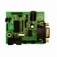
STEVAL-ISQ002V1
Manufacturer Part Number
STEVAL-ISQ002V1
Description
BOARD EVAL BASED ON ST72264G1
Manufacturer
STMicroelectronics
Specifications of STEVAL-ISQ002V1
Main Purpose
Interface, PMBus
Embedded
Yes, MCU, 8-Bit
Utilized Ic / Part
ST72F264
Primary Attributes
The PMBus™ Interface Using the ST7 I2C Peripheral
Secondary Attributes
Firmware in C Language
Product
Power Management Modules
Lead Free Status / RoHS Status
Lead free / RoHS Compliant
Other names
497-6423
Available stocks
Company
Part Number
Manufacturer
Quantity
Price
Company:

Part Number:
STEVAL-ISQ002V1
Manufacturer:
STMicroelectronics
Quantity:
1


FLASH PROGRAM MEMORY (Cont’d)
4.4 ICC interface
ICP needs a minimum of 4 and up to 7 pins to be
connected to the programming tool. These pins
are:
Notes:
1. If the ICCCLK or ICCDATA pins are only used
as outputs in the application, no signal isolation is
necessary. As soon as the Programming Tool is
plugged to the board, even if an ICC session is not
in progress, the ICCCLK and ICCDATA pins are
not available for the application. If they are used as
inputs by the application, isolation such as a serial
resistor has to be implemented in case another de-
vice forces the signal. Refer to the Programming
Figure 6. Typical ICC Interface
– RESET: device reset
– V
– ICCCLK: ICC output serial clock pin
– ICCDATA: ICC input serial data pin
– ICCSEL: ICC selection (not required on devic-
– OSC1: main clock input for external source
– V
APPLICATION
POWER SUPPLY
es without ICCSEL pin)
(not required on devices without OSC1/OSC2
pins)
al, see Note 3)
SS
DD
: device power supply ground
: application board power supply (option-
(See Note 3)
C
L2
OPTIONAL
(See Note 4)
C
ST7
L1
HE10 CONNECTOR TYPE
10kΩ
10
ICC CONNECTOR
9
PROGRAMMING TOOL
Tool documentation for recommended resistor val-
ues.
2. During the ICP session, the programming tool
must control the RESET pin. This can lead to con-
flicts between the programming tool and the appli-
cation reset circuit if it drives more than 5mA at
high level (push pull output or pull-up resistor<1K).
A schottky diode can be used to isolate the appli-
cation RESET circuit in this case. When using a
classical RC network with R>1K or a reset man-
agement IC with open drain output and pull-up re-
sistor>1K, no additional components are needed.
In all cases the user must ensure that no external
reset is generated by the application during the
ICC session.
3. The use of Pin 7 of the ICC connector depends
on the Programming Tool architecture. This pin
must be connected when using most ST Program-
ming Tools (it is used to monitor the application
power supply). Please refer to the Programming
Tool manual.
4. Pin 9 has to be connected to the OSC1 pin of
the ST7 when the clock is not available in the ap-
plication or if the selected clock option is not pro-
grammed in the option byte. ST7 devices with mul-
ti-oscillator capability need to have OSC2 ground-
ed in this case.
7
8
ICC CONNECTOR
5
6
ST72260Gx, ST72262Gx, ST72264Gx
4
3
ICC Cable
1
2
APPLICATION BOARD
See Note 2
APPLICATION
RESET SOURCE
See Note 1
APPLICATION
I/O
15/172
Related parts for STEVAL-ISQ002V1
Image
Part Number
Description
Manufacturer
Datasheet
Request
R

Part Number:
Description:
BOARD RGB CTR ST7,STP08C596MTR
Manufacturer:
STMicroelectronics
Datasheet:

Part Number:
Description:
Power Management IC Development Tools Full Speed USB to RS232 Bridge Demo
Manufacturer:
STMicroelectronics
Datasheet:
Part Number:
Description:
Power Management IC Development Tools 2.5W solar eval BRD USB SPV1040 LD39050
Manufacturer:
STMicroelectronics
Datasheet:

Part Number:
Description:
BOARD EVAL FOR MEMS SENSORS
Manufacturer:
STMicroelectronics
Datasheet:

Part Number:
Description:
KIT DEV STARTER ST10F276Z5
Manufacturer:
STMicroelectronics
Datasheet:

Part Number:
Description:
BOARD EVAL HDMI $ VIDEO SWITCH
Manufacturer:
STMicroelectronics
Datasheet:

Part Number:
Description:
BOARD DEMO ACCELEROMETER DIL24
Manufacturer:
STMicroelectronics
Datasheet:

Part Number:
Description:
BOARD STLM75/STDS75/ST72F651
Manufacturer:
STMicroelectronics
Datasheet:

Part Number:
Description:
EVAL BOARD 3AXIS MEMS ACCELLRMTR
Manufacturer:
STMicroelectronics
Datasheet:

Part Number:
Description:
BOARD EVAL 8BIT MICRO + TDE1708
Manufacturer:
STMicroelectronics
Datasheet:
Part Number:
Description:
STMicroelectronics [RIPPLE-CARRY BINARY COUNTER/DIVIDERS]
Manufacturer:
STMicroelectronics
Datasheet:
Part Number:
Description:
STMicroelectronics [LIQUID-CRYSTAL DISPLAY DRIVERS]
Manufacturer:
STMicroelectronics
Datasheet:
Part Number:
Description:
BOARD EVAL FOR MEMS SENSORS
Manufacturer:
STMicroelectronics
Datasheet: