STEVAL-ISQ002V1 STMicroelectronics, STEVAL-ISQ002V1 Datasheet - Page 117
STEVAL-ISQ002V1
Manufacturer Part Number
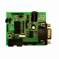
STEVAL-ISQ002V1
Description
BOARD EVAL BASED ON ST72264G1
Manufacturer
STMicroelectronics
Specifications of STEVAL-ISQ002V1
Main Purpose
Interface, PMBus
Embedded
Yes, MCU, 8-Bit
Utilized Ic / Part
ST72F264
Primary Attributes
The PMBus™ Interface Using the ST7 I2C Peripheral
Secondary Attributes
Firmware in C Language
Product
Power Management Modules
Lead Free Status / RoHS Status
Lead free / RoHS Compliant
Other names
497-6423
Available stocks
Company
Part Number
Manufacturer
Quantity
Price
Company:

Part Number:
STEVAL-ISQ002V1
Manufacturer:
STMicroelectronics
Quantity:
1


10-BIT A/D CONVERTER (ADC) (Cont’d)
11.7.3.2 Digital A/D Conversion Result
The conversion is monotonic, meaning that the re-
sult never decreases if the analog input does not
and never increases if the analog input does not.
If the input voltage (V
(high-level voltage reference) then the conversion
result is FFh in the ADCDRH register and 03h in
the ADCDRL register (without overflow indication).
If the input voltage (V
level voltage reference) then the conversion result
in the ADCDRH and ADCDRL registers is 00 00h.
The A/D converter is linear and the digital result of
the conversion is stored in the ADCDRH and AD-
CDRL registers. The accuracy of the conversion is
described in the Electrical Characteristics Section.
R
for an analog input signal. If the impedance is too
high, this will result in a loss of accuracy due to
leakage and sampling not being completed in the
alloted time.
11.7.3.3 A/D Conversion
The analog input ports must be configured as in-
put, no pull-up, no interrupt. Refer to the «I/O
ports» chapter. Using these pins as analog inputs
does not affect the ability of the port to be read as
a logic input.
In the ADCCSR register:
– Select the CH[2:0] bits to assign the analog
ADC Conversion mode
In the ADCCSR register:
- Set the SPEED or the SLOW bits
– Set the ADON bit to enable the A/D converter
AIN
channel to convert.
and to start the conversion. From this time on,
the ADC performs a continuous conversion of
the selected channel.
is the maximum recommended impedance
AIN
AIN
) is lower than V
) is greater than V
SSA
(low-
DDA
When a conversion is complete:
A read to the ADCDRH or a write to any bit of the
ADCCSR resets the EOC bit.
To read the 10 bits, perform the following steps:
1. Poll EOC bit
2. Read ADCDRL. This locks the ADCDRH until it
3. Read ADCDRH. This clears EOC automati-
To read only 8 bits, perform the following steps:
1. Poll EOC bit
2. Read ADCDRH. This clears EOC automati-
11.7.4 Low Power Modes
Note: The A/D converter may be disabled by re-
setting the ADON bit. This feature allows reduced
power consumption when no conversion is need-
ed and between single shot conversions.
11.7.5 Interrupts
None.
Mode
WAIT
HALT
– The EOC bit is set by hardware.
– The result is in the ADCDR registers.
is read.
cally.
cally.
ST72260Gx, ST72262Gx, ST72264Gx
Description
No effect on A/D Converter
A/D Converter disabled.
After wakeup from Halt mode, the A/D
Converter requires a stabilization time
t
before accurate conversions can be
performed.
STAB
(see Electrical Characteristics)
117/172
Related parts for STEVAL-ISQ002V1
Image
Part Number
Description
Manufacturer
Datasheet
Request
R

Part Number:
Description:
BOARD RGB CTR ST7,STP08C596MTR
Manufacturer:
STMicroelectronics
Datasheet:

Part Number:
Description:
Power Management IC Development Tools Full Speed USB to RS232 Bridge Demo
Manufacturer:
STMicroelectronics
Datasheet:
Part Number:
Description:
Power Management IC Development Tools 2.5W solar eval BRD USB SPV1040 LD39050
Manufacturer:
STMicroelectronics
Datasheet:

Part Number:
Description:
BOARD EVAL FOR MEMS SENSORS
Manufacturer:
STMicroelectronics
Datasheet:

Part Number:
Description:
KIT DEV STARTER ST10F276Z5
Manufacturer:
STMicroelectronics
Datasheet:

Part Number:
Description:
BOARD EVAL HDMI $ VIDEO SWITCH
Manufacturer:
STMicroelectronics
Datasheet:

Part Number:
Description:
BOARD DEMO ACCELEROMETER DIL24
Manufacturer:
STMicroelectronics
Datasheet:

Part Number:
Description:
BOARD STLM75/STDS75/ST72F651
Manufacturer:
STMicroelectronics
Datasheet:

Part Number:
Description:
EVAL BOARD 3AXIS MEMS ACCELLRMTR
Manufacturer:
STMicroelectronics
Datasheet:

Part Number:
Description:
BOARD EVAL 8BIT MICRO + TDE1708
Manufacturer:
STMicroelectronics
Datasheet:
Part Number:
Description:
STMicroelectronics [RIPPLE-CARRY BINARY COUNTER/DIVIDERS]
Manufacturer:
STMicroelectronics
Datasheet:
Part Number:
Description:
STMicroelectronics [LIQUID-CRYSTAL DISPLAY DRIVERS]
Manufacturer:
STMicroelectronics
Datasheet:
Part Number:
Description:
BOARD EVAL FOR MEMS SENSORS
Manufacturer:
STMicroelectronics
Datasheet: