MA330013 Microchip Technology, MA330013 Datasheet - Page 215
MA330013
Manufacturer Part Number
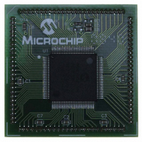
MA330013
Description
MODULE PLUG-IN DSPIC33 100TQFP
Manufacturer
Microchip Technology
Specifications of MA330013
Accessory Type
Plug-In Module (PIM) - dsPIC33FJ256MC710
Tool / Board Applications
General Purpose MCU, MPU, DSP, DSC
Mcu Supported Families
DsPIC33
Silicon Manufacturer
Microchip
Core Architecture
DsPIC
Core Sub-architecture
DsPIC33
Silicon Core Number
DsPIC33F
Silicon Family Name
DsPIC33FJxxMCxxx
Rohs Compliant
Yes
For Use With
DM330023 - BOARD DEV DSPICDEM MCHV
Lead Free Status / RoHS Status
Not applicable / Not applicable
For Use With/related Products
Explorer 16 (DM240001 or DM240002)
Lead Free Status / RoHS Status
Lead free / RoHS Compliant, Not applicable / Not applicable


18.0
The Inter-Integrated Circuit (I
complete hardware support for both Slave and Multi-
Master modes of the I
standard, with a 16-bit interface.
The dsPIC33F devices have up to two I
modules, denoted as I2C1 and I2C2. Each I
has a 2-pin interface: the SCLx pin is clock and the
SDAx pin is data.
Each I
features:
• I
• I
• I
• I
• Serial clock synchronization for I
• I
18.1
The hardware fully implements all the master and slave
functions of the I
specifications, as well as 7 and 10-bit addressing.
The I
master on an I
The following types of I
• I
• I
• I
For details about the communication sequence in each
of these modes, please refer to the “dsPIC30F Family
Reference Manual”.
© 2007 Microchip Technology Inc.
Note:
operation.
master and slaves.
used as a handshake mechanism to suspend and
resume serial transfer (SCLREL control).
collision and will arbitrate accordingly.
2
2
2
2
2
2
2
2
C interface supporting both master and slave
C Slave mode supports 7 and 10-bit address.
C Master mode supports 7 and 10-bit address.
C port allows bidirectional transfers between
C supports multi-master operation; detects bus
C slave operation with 7-bit address
C slave operation with 10-bit address
C master operation with 7 or 10-bit address
2
2
C module can operate either as a slave or a
C module ‘x’ (x = 1 or 2) offers the following key
INTER-INTEGRATED CIRCUIT
(I
Operating Modes
2
This data sheet summarizes the features
of this group of dsPIC33F devices. It is not
intended to be a comprehensive reference
source. To complement the information in
this data sheet, refer to the “dsPIC30F
Family Reference Manual” (DS70046).
C)
2
C bus.
2
C Standard and Fast mode
2
C operation are supported:
2
C serial communication
2
C) module provides
2
C port can be
2
C interface
2
C module
Preliminary
18.2
I2CxCON and I2CxSTAT are control and status
registers, respectively. The I2CxCON register is
readable and writable. The lower six bits of I2CxSTAT
are read-only. The remaining bits of the I2CSTAT are
read/write.
I2CxRSR is the shift register used for shifting data,
whereas I2CxRCV is the buffer register to which data
bytes are written, or from which data bytes are read.
I2CxRCV is the receive buffer. I2CxTRN is the transmit
register to which bytes are written during a transmit
operation.
The I2CxADD register holds the slave address. A
status bit, ADD10, indicates 10-bit Address mode. The
I2CxBRG acts as the Baud Rate Generator (BRG)
reload value.
In receive operations, I2CxRSR and I2CxRCV together
form a double-buffered receiver. When I2CxRSR
receives a complete byte, it is transferred to I2CxRCV
and an interrupt pulse is generated.
18.3
The I
(I
Slave Events Interrupt Flag). A separate interrupt is
generated for all I
18.4
In I
located in the I2CxBRG register. When the BRG is
loaded with this value, the BRG counts down to ‘0’ and
stops until another reload has taken place. If clock arbi-
tration is taking place, for instance, the BRG is reloaded
when the SCLx pin is sampled high.
As per the I
400 kHz. However, the user can specify any baud rate
up to 1 MHz. I2CxBRG values of ‘0’ or ‘1’ are illegal.
EQUATION 18-1:
2
C Master Events Interrupt Flag) and SI2CxIF (I
2
C Master mode, the reload value for the BRG is
2
C module generates two interrupt flags, MI2CxIF
I
I
Baud Rate Generator
2
2
I2CxBRG =
C Registers
C Interrupts
2
C standard, F
2
C error conditions.
(
SERIAL CLOCK RATE
F
F
SCL
CY
SCL
dsPIC33F
–
1,111,111
may be 100 kHz or
F
CY
DS70165E-page 213
)
– 1
2
C
Related parts for MA330013
Image
Part Number
Description
Manufacturer
Datasheet
Request
R

Part Number:
Description:
Manufacturer:
Microchip Technology Inc.
Datasheet:
Part Number:
Description:
Manufacturer:
Microchip Technology Inc.
Datasheet:
Part Number:
Description:
Manufacturer:
Microchip Technology Inc.
Datasheet:
Part Number:
Description:
Manufacturer:
Microchip Technology Inc.
Datasheet:
Part Number:
Description:
Manufacturer:
Microchip Technology Inc.
Datasheet:
Part Number:
Description:
Manufacturer:
Microchip Technology Inc.
Datasheet:
Part Number:
Description:
Manufacturer:
Microchip Technology Inc.
Datasheet:
Part Number:
Description:
Manufacturer:
Microchip Technology Inc.
Datasheet: