MT18VDDF12872Y-40BF1 Micron Technology Inc, MT18VDDF12872Y-40BF1 Datasheet - Page 22
MT18VDDF12872Y-40BF1
Manufacturer Part Number
MT18VDDF12872Y-40BF1
Description
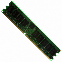
MODULE DDR SDRAM 1GB 184-DIMM
Manufacturer
Micron Technology Inc
Specifications of MT18VDDF12872Y-40BF1
Memory Type
DDR SDRAM
Memory Size
1GB
Speed
400MT/s
Package / Case
184-DIMM
Main Category
DRAM Module
Sub-category
DDR SDRAM
Module Type
184RDIMM
Device Core Size
72b
Organization
128Mx72
Total Density
1GByte
Chip Density
512Mb
Access Time (max)
700ps
Maximum Clock Rate
400MHz
Operating Supply Voltage (typ)
2.6V
Operating Current
1.8A
Number Of Elements
18
Operating Supply Voltage (max)
2.7V
Operating Supply Voltage (min)
2.5V
Operating Temp Range
0C to 70C
Operating Temperature Classification
Commercial
Pin Count
184
Mounting
Socket
Lead Free Status / RoHS Status
Lead free / RoHS Compliant
Other names
557-1233
MT18VDDF12872Y-40BF1
MT18VDDF12872Y-40BF1


Table 15: PLL Clock Driver Timing Requirements and Switching Characteristics
Note: 1
NOTE:
pdf: 09005aef80f6b913, source: 09005aef80f6b41c
DDAF18C64_128x72G.fm - Rev. C 9/04 EN
PARAMETER
Operating Clock Frequency
Input Duty Cycle
Stabilization Time
Cycle to Cycle Jitter
Static Phase Offset
Output Clock Skew
Period Jitter
Half-Period Jitter
Input Clock Slew Rate
Output Clock Slew Rate
1. The timing and switching specifications for the PLL listed above are critical for proper operation of DDR SDRAM Regis-
2. The PLL must be able to handle spread spectrum induced skew.
3. Operating clock frequency indicates a range over which the PLL must be able to lock, but in which it is not required to
4. Stabilization time is the time required for the integrated PLL circuit to obtain phase lock of its feedback signal to its ref-
5. Static Phase Offset does not include Jitter.
6. Period Jitter and Half-Period Jitter specifications are separate specifications that must be met independently of each
7. The Output Slew Rate is determined from the IBIS model:
tered DIMMs. These are meant to be a subset of the parameters for the specific device used on the module. Detailed
information for this PLL is available in JEDEC Standard JESD82.
meet the other timing parameters. (Used for low speed system debug.)
erence signal after power up.
other.
SYMBOL
t
t
t
JIT
t
STAB
JIT
t
t
t
JIT
f
t
SK
t
LS
DC
CK
LS
HPER
PER
CC
O
O
I
MIN
-100
-75
-50
-75
1.0
1.0
60
40
-
-
V
22
0°C
DD
512MB, 1GB (x72, ECC, SR) PC3200
NOMINAL
CDCV857
= +2.6V ±0.1V
GND
T
0
V
-
-
-
-
-
-
-
-
-
DD
A
Micron Technology, Inc., reserves the right to change products or specifications without notice.
184-PIN DDR SDRAM RDIMM
+70°C
MAX
V
V
220
100
100
100
CK
CK
60
75
50
75
4
2
R=60
R=60
V
DD
/2
©2004 Micron Technology, Inc. All rights reserved.
UNITS
MHz
V/ns
V/ns
ms
%
ps
ps
ps
ps
ps
NOTES
2, 3
4
5
6
6
7
Related parts for MT18VDDF12872Y-40BF1
Image
Part Number
Description
Manufacturer
Datasheet
Request
R

Part Number:
Description:
IC SDRAM 64MBIT 133MHZ 54TSOP
Manufacturer:
Micron Technology Inc
Datasheet:

Part Number:
Description:
IC SDRAM 64MBIT 5.5NS 86TSOP
Manufacturer:
Micron Technology Inc
Datasheet:
Part Number:
Description:
IC SDRAM 64MBIT 200MHZ 86TSOP
Manufacturer:
Micron Technology Inc
Datasheet:
Part Number:
Description:
IC SDRAM 64MBIT 133MHZ 54TSOP
Manufacturer:
Micron Technology Inc
Datasheet:
Part Number:
Description:
IC SDRAM 128MBIT 133MHZ 54TSOP
Manufacturer:
Micron Technology Inc
Datasheet:

Part Number:
Description:
IC SDRAM 256MBIT 133MHZ 90VFBGA
Manufacturer:
Micron Technology Inc
Datasheet:
Part Number:
Description:
IC SDRAM 128MBIT 133MHZ 54TSOP
Manufacturer:
Micron Technology Inc
Datasheet:
Part Number:
Description:
IC SDRAM 256MBIT 133MHZ 54TSOP
Manufacturer:
Micron Technology Inc
Datasheet:

Part Number:
Description:
IC DDR SDRAM 512MBIT 6NS 66TSOP
Manufacturer:
Micron Technology Inc
Datasheet:
Part Number:
Description:
IC SDRAM 128MBIT 167MHZ 86TSOP
Manufacturer:
Micron Technology Inc
Datasheet:
Part Number:
Description:
IC SDRAM 128MBIT 143MHZ 86TSOP
Manufacturer:
Micron Technology Inc
Datasheet:

Part Number:
Description:
SDRAM 256M-BIT 1.8V 54-PIN VFBGA
Manufacturer:
Micron Technology Inc
Datasheet:
Part Number:
Description:
IC SDRAM 128MBIT 143MHZ 86TSOP
Manufacturer:
Micron Technology Inc
Datasheet:

Part Number:
Description:
IC SDRAM 128MBIT 125MHZ 54VFBGA
Manufacturer:
Micron Technology Inc
Datasheet:
Part Number:
Description:
IC SDRAM 128MBIT 125MHZ 54VFBGA
Manufacturer:
Micron Technology Inc
Datasheet: