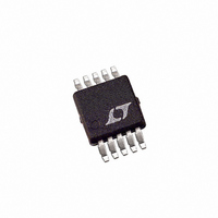
LTC3809EMSE-1 Linear Technology, LTC3809EMSE-1 Datasheet - Page 18

LTC3809EMSE-1
Manufacturer Part Number
LTC3809EMSE-1
Description
IC CTRLR DC/DC SYNC 10-MSOP
Manufacturer
Linear Technology
Type
Step-Down (Buck)r
Datasheet
1.LTC3809EMSE-1PBF.pdf
(24 pages)
Specifications of LTC3809EMSE-1
Internal Switch(s)
No
Synchronous Rectifier
Yes
Number Of Outputs
1
Voltage - Output
0.6 ~ 9.8 V
Current - Output
1A
Frequency - Switching
550kHz
Voltage - Input
2.75 ~ 9.8 V
Operating Temperature
-40°C ~ 85°C
Mounting Type
Surface Mount
Package / Case
10-MSOP Exposed Pad, 10-HMSOP, 10-eMSOP
Lead Free Status / RoHS Status
Contains lead / RoHS non-compliant
Power - Output
-
Available stocks
Company
Part Number
Manufacturer
Quantity
Price
Company:
Part Number:
LTC3809EMSE-1
Manufacturer:
LT
Quantity:
10 000
Company:
Part Number:
LTC3809EMSE-1#PBF
Manufacturer:
Linear Technology
Quantity:
135
APPLICATIONS INFORMATION
LTC3809-1
The auxiliary output voltage V
in Figure 6, by the turns ratio N of the transformer:
However, if the controller goes into pulse-skipping operation
and halts switching due to a light primary load current, then
V
the MODE sets a minimum voltage V
If V
temporary continuous switching operation until V
again above its minimum.
Fault Condition: Short-Circuit and Current Limit
If the LTC3809-1’s load current exceeds the short-circuit
current limit (I
threshold (ΔV
bottom N-channel MOSFET, the top P-channel MOSFET
is turned off and will not be turned on at the next clock
cycle unless the load current decreases below I
case, the controller’s switching frequency is decreased
and the output is regulated by short-circuit (current limit)
protection.
18
AUX
V
V
AUX
AUX
AUX MIN
will droop. An external resistor divider from V
drops below this value, the MODE voltage forces
= (N + 1) • V
(
R6
R5
Figure 6. Auxiliary Output Loop Connection
MODE
)
LTC3809-1
=
SC
SC
0 4
), which is set by the short-circuit sense
) and the on resistance (R
.
SW
TG
BG
V
OUT
•
⎛
⎜
⎝
1
+
V
IN
R
R
AUX
6
5
⎞
⎟
⎠
is normally set, as shown
1:N
L1
AUX(MIN)
+
+
C
1μF
OUT
38091 F06
:
V
V
DS(ON)
AUX
OUT
SC
. In this
AUX
AUX
) of
to
is
In a hard short (V
is turned off and kept off until the short-circuit condition
is cleared. In this case, there is no current path from
input supply (V
excessive MOSFET and inductor heating.
Low Supply Voltage
Although the LTC3809-1 can function down to below 2.4V,
the maximum allowable output current is reduced as V
decreases below 3V. Figure 7 shows the amount of change
as the supply is reduced down to 2.4V. Also shown is the
effect on V
Minimum On-Time Considerations
Minimum on-time, t
that the LTC3809-1 is capable of turning the top P-channel
MOSFET on. It is determined by internal timing delays and
the gate charge required to turn on the top MOSFET. Low
duty cycle and high frequency applications may approach
the minimum on-time limit and care should be taken to
ensure that:
Figure 7. Line Regulation of V
t
ON MIN
(
)
REF
105
100
<
95
90
85
80
75
.
2.0
f
OSC
IN
V
) to either V
2.1
OUT
OUT
•
V
ON(MIN)
2.2
REF
V
IN
= 0V), the top P-channel MOSFET
2.3
INPUT VOLTAGE (V)
MAXIMUM
SENSE VOLTAGE
2.4
REF
is the smallest amount of time
OUT
2.5
and Maximum Sense Voltage
2.6
or GND, which prevents
2.7
2.8
38091 F07
2.9
3.0
38091fc
IN


