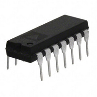
AD650JNZ Analog Devices Inc, AD650JNZ Datasheet - Page 18

AD650JNZ
Manufacturer Part Number
AD650JNZ
Description
IC V-F/F-V CONVERTER 14-DIP
Manufacturer
Analog Devices Inc
Type
Volt to Freq & Freq to Voltr
Datasheet
1.AD650KNZ.pdf
(20 pages)
Specifications of AD650JNZ
Mounting Type
Through Hole
Frequency - Max
1MHz
Full Scale
±150ppm/°C
Linearity
±0.1%
Package / Case
14-DIP (0.300", 7.62mm)
Frequency
1MHz
Full Scale Range
1MHz
Linearity %
0.02%
Supply Voltage Range
± 9V To ± 18V
Digital Ic Case Style
DIP
No. Of Pins
14
Ic Generic Number
650
Converter Function
VFC/FVC
Full Scale Frequency
1000
Power Supply Requirement
Dual
Single Supply Voltage (typ)
Not RequiredV
Single Supply Voltage (max)
Not RequiredV
Single Supply Voltage (min)
Not RequiredV
Dual Supply Voltage (min)
±9V
Dual Supply Voltage (max)
±18V
Operating Temperature (min)
0C
Operating Temperature (max)
70C
Operating Temperature Classification
Commercial
Package Type
PDIP
Calibration Error Fs Typ
5%
Rohs Compliant
Yes
Lead Free Status / RoHS Status
Lead free / RoHS Compliant
Lead Free Status / RoHS Status
Lead free / RoHS Compliant, Lead free / RoHS Compliant
Available stocks
Company
Part Number
Manufacturer
Quantity
Price
Company:
Part Number:
AD650JNZ
Manufacturer:
AD
Quantity:
1 000
Company:
Part Number:
AD650JNZ
Manufacturer:
LINEAR
Quantity:
7 838
Part Number:
AD650JNZ
Manufacturer:
ADI/亚德诺
Quantity:
20 000
AD650
In signal recovery applications of a PLL, the desired output
signal is the voltage applied to the oscillator. In these situations,
a linear relationship between the input frequency and the
output voltage is desired; the AD650 makes a superb oscillator
for FM demodulation. The wide dynamic range and
outstanding linearity of the AD650 VFC allow simple
embodiment of high performance analog signal isolation or
telemetry systems. The circuit shown in Figure 22 uses a digital
phase detector that also provides proper feedback in the event
of unequal frequencies. Such phase-frequency detectors (PFDs)
are available in integrated form. For a full discussion of phase-
lock loop circuits see “Phase Lock Techniques, ” 3
F.M. Gardner, (John Wiley & Sons, Inc., 1979).
An analysis of this circuit must begin at the 7474 Dual D flip
flop. When the input carrier matches the output carrier in both
phase and frequency, the Q outputs of the flip flops rise at
exactly the same time. With two zeros, and then two ones on
the inputs of the exclusive or (XOR) gate, the output remains
low keeping the DMOS FET switched off. Also, the NAND gate
goes low resetting the flip-flops to zero. Throughout this entire
cycle, the DMOS integrator gate remains off, allowing the
voltage at the integrator output to remain unchanged from the
previous cycle. However, if the input carrier leads the output
carrier by a few degrees, the XOR gate is turned on for the short
time span that the two signals are mismatched. Because Q
low during the mismatch time, a negative current is fed into the
integrator, causing its output voltage to rise. This in turn
increases the frequency of the AD650 slightly, driving the
system towards synchronization. In a similar manner, if the
input carrier lags the output carrier, the integrator is forced
down slightly to synchronize the two signals.
Using a mathematical approach, the ±25 μA pulses from the
phase detector are incorporated into the phase-detector gain (K
Also, the V/F converter is configured to produce 1 MHz in
response to a 10 V input so its gain (Ko) is
The dynamics of the phase relationship between the input and
output signals can be characterized as a second order system
with natural frequency (ω
K
K
d
O
=
=
25
2
2
π
μA
π
×
1
10
×
=
10
V
4
×
6
10
Hz
−
n
6
=
).
amperes
6
3 .
×
10
5
/
volt
radian
radians
×
sec
rd
Edition, by
2
is
(10)
Rev. D | Page 18 of 20
(9)
d
).
and damping factor (ζ) is
For the values shown in Figure 22, these relations simplify to a
natural frequency of 35 kHz with a damping factor of 0.8.
For a simple approach to determine component values for other
PLL frequencies and VFC full-scale voltage, follow these steps:
1.
2.
3.
If in actual operation the PLL overshoots or hunts excessively
before reaching a final value, the damping factor can be raised
by increasing the value of R. Conversely, if the PLL is
overdamped, a smaller value of R should be used.
where:
C units = farads
f
K
where:
R units = ohms
f
K
n
n
Determine K
maximum input carrier frequency f
maximum output voltage V
Calculate a value for C based upon the desired loop
bandwidth f
of the output signal. The loop bandwidth (f
maximum carrier frequency (f
narrow even though it is transmitted over a 1 MHz carrier.
Calculate R to yield a damping factor of approximately 0.8
using this equation:
ω
ζ
K
C
R
o
o
units = hertz
units = hertz
units = rad/volt × sec
units = rad/volt × sec
n
=
o
=
=
=
=
R
K
K
f
f
2
n
n
o
o
2
π
K
CK
V
×
×
×
2
o
C
2
MAX
1
K
F
5 .
o
×
MAX
n
K
d
. Note that this is the desired frequency range
o
×
10
d
(in units of radians per volt second) from the
10
−
7
6
Rad
Rad
V
V
×
×
×
F
sec
Ω
MAX
MAX
.
). The signal can be very
MAX
(in hertz) and the
n
) is not the
(11)
(12)
(13)
(14)
(15)


