ADT7517ARQZ Analog Devices Inc, ADT7517ARQZ Datasheet - Page 42
ADT7517ARQZ
Manufacturer Part Number
ADT7517ARQZ
Description
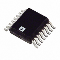
IC SENSOR TEMP QD ADC/DAC 16QSOP
Manufacturer
Analog Devices Inc
Datasheet
1.ADT7517ARQZ.pdf
(44 pages)
Specifications of ADT7517ARQZ
Function
Temp Monitoring System (Sensor)
Topology
ADC, Comparator, Multiplexer, Register Bank
Sensor Type
External & Internal
Sensing Temperature
-40°C ~ 120°C, External Sensor
Output Type
I²C™, MICROWIRE™, QSPI™, SPI™
Output Alarm
No
Output Fan
No
Voltage - Supply
2.7 V ~ 5.5 V
Operating Temperature
-40°C ~ 120°C
Mounting Type
Surface Mount
Package / Case
16-QSOP
Ic Output Type
Voltage
Sensing Accuracy Range
± 0.5°C
Supply Current
2.2mA
Supply Voltage Range
2.7V To 5.5V
Resolution (bits)
10bit
Sensor Case Style
QSOP
No. Of Pins
16
Temperature Sensor Function
Temp Sensor
Resolution
10b
Operating Temperature (min)
-40C
Operating Temperature (max)
120C
Operating Supply Voltage (min)
2.7V
Operating Supply Voltage (typ)
3.3/5V
Operating Supply Voltage (max)
5.5V
Lead Free Status / RoHS Status
Lead free / RoHS Compliant
Lead Free Status / RoHS Status
Lead free / RoHS Compliant, Lead free / RoHS Compliant
Available stocks
Company
Part Number
Manufacturer
Quantity
Price
Company:

Part Number:
ADT7517ARQZ
Manufacturer:
Analog Devices Inc
Quantity:
135


ADT7516/ADT7517/ADT7519
SMBus/SPI INT/ INT
The ADT7516/ADT7517/ADT7519 INT/ INT outputs are an
interrupt line for devices that want to trade their ability to
master for an extra pin. The ADT7516/ADT7517/ADT7519 are
slave devices and use the SMBus/SPI INT/ INT to signal the host
device that it wants to talk to. The SMBus/SPI INT/ INT on the
ADT7516/ADT7517/ADT7519 is used as an over/under limit
indicator.
The INT/ INT pin has an open-drain configuration that allows the
outputs of several devices to be wire-AND’ e d together when the
INT/ INT pin is active low. Use C6 of the Control Configuration 1
register to set the active polarity of the INT/ INT output. The
power-up default is active low. The INT/ INT output can be
disabled or enabled by setting C5 of the Control Configuration 1
register to 1 or 0, respectively.
The INT/ INT output becomes active when either the internal
temperature value, the external temperature value, V
any of the AIN input values exceed the values in their
corresponding T
INT/ INT output goes inactive again when a conversion result
has the measured value back within the trip limits and when the
status register associated with the out-of-limit event is read. The
two interrupt status registers show the event that caused the
INT/ INT pin to go active.
The INT/ INT output requires an external pull-up resistor. This
can be connected to a voltage different from V
maximum voltage rating of the INT/ INT output pin is not
exceeded. The value of the pull-up resistor depends on the
application but should be large enough to avoid excessive sink
currents at the INT/ INT output because they can heat the chip
and affect the temperature reading.
SMBUS ALERT RESPONSE
The INT/ INT pin behaves the same way as an SMBus alert pin
when the SMBus/I
output and requires a pull-up to V
can be wire-AND’ e d together, so that the common line goes low
if one or more of the INT/ INT outputs goes low. The polarity of
the INT/ INT pin must be set active low for a number of outputs
to be wire-AND’ e d together.
The INT/ INT output can operate as an SMBALERT function.
Slave devices on the SMBus cannot normally signal to the
master that they want to talk, but the SMBALERT function
HIGH
2
C interface is selected. It is an open-drain
/V
HIGH
or T
LOW
DD
/V
. Several INT/ INT outputs
LOW
registers. The
DD
, provided the
DD
value, or
Rev. B | Page 42 of 44
allows them to do so. SMBALERT is used in conjunction with
the SMBus general call address.
One or more INT/ INT outputs can be connected to a common
SMBALERT line connected to the master. When the
SMBALERT line is pulled low by one of the devices, the
following procedure occurs as shown in Figure 68:
1.
2.
3.
4.
5.
START
MASTER
RECEIVES
SMBALERT
START ALERT RESPONSE
SMBALERT is pulled low.
Master initiates a read operation and sends the alert
response address (ARA = 0001 100). This general call
address must not be used as a specific device address.
A device whose INT/ INT output is low responds to the
alert response address and the master reads its device
address. As the device address is seven bits long, an LSB of
1 is added. The address of the device is now known and it
can be interrogated in the usual way.
If INT/ INT output of more than one device is low, the one
with the lowest device address has priority in accordance
with normal SMBus specifications.
When the ADT7516/ADT7517/ADT7519 have responded
to the alert response address, they reset their INT/ INT
output, provided that the condition that caused the out-of-
limit event no longer exists and that the status register
associated with the out-of-limit event is read. If the
SMBALERT line remains low, the master sends the ARA
again. It continues to do this until all devices whose
SMBALERT outputs were low have responded.
MASTER
RECEIVES
SMBALERT
ALERT RESPONSE
MASTER SENDS
ARA AND READ
MASTER SENDS
ARA AND READ
ADDRESS
Figure 68. INT/ INT Responds to SMBALERT ARA
Figure 69. INT/ INT Responds to SMBALERT ARA
COMMAND
ADDRESS
COMMAND
with Packet Error Checking (PEC)
RD ACK
DEVICE ACK
RD ACK DEVICE ADDRESS
DEVICE SENDS
ITS ADDRESS
ADDRESS
DEVICE
DEVICE SENDS
ITS ADDRESS
MASTER
ACK
ACK
DEVICE SENDS
ITS PEC DATA
PEC
ACK STOP
NO
MASTER
NACK
ACK
NO
STOP
Related parts for ADT7517ARQZ
Image
Part Number
Description
Manufacturer
Datasheet
Request
R

Part Number:
Description:
±1.7g Dual-Axis IMEMS Accelerometer Evaluation Board
Manufacturer:
Analog Devices Inc
Datasheet:

Part Number:
Description:
Inertial Sensor Evaluation System
Manufacturer:
Analog Devices Inc
Datasheet:
Part Number:
Description:
Manufacturer:
Analog Devices Inc
Datasheet:
Part Number:
Description:
Manufacturer:
Analog Devices Inc
Datasheet:
Part Number:
Description:
Manufacturer:
Analog Devices Inc
Datasheet:
Part Number:
Description:
Manufacturer:
Analog Devices Inc
Datasheet:
Part Number:
Description:
Manufacturer:
Analog Devices Inc
Datasheet:
Part Number:
Description:
Manufacturer:
Analog Devices Inc
Datasheet:
Part Number:
Description:
Manufacturer:
Analog Devices Inc
Datasheet:
Part Number:
Description:
Manufacturer:
Analog Devices Inc
Datasheet:
Part Number:
Description:
Manufacturer:
Analog Devices Inc
Datasheet:
Part Number:
Description:
Manufacturer:
Analog Devices Inc
Datasheet:
Part Number:
Description:
Manufacturer:
Analog Devices Inc
Datasheet: