ADT7517ARQZ Analog Devices Inc, ADT7517ARQZ Datasheet - Page 31
ADT7517ARQZ
Manufacturer Part Number
ADT7517ARQZ
Description
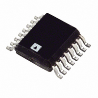
IC SENSOR TEMP QD ADC/DAC 16QSOP
Manufacturer
Analog Devices Inc
Datasheet
1.ADT7517ARQZ.pdf
(44 pages)
Specifications of ADT7517ARQZ
Function
Temp Monitoring System (Sensor)
Topology
ADC, Comparator, Multiplexer, Register Bank
Sensor Type
External & Internal
Sensing Temperature
-40°C ~ 120°C, External Sensor
Output Type
I²C™, MICROWIRE™, QSPI™, SPI™
Output Alarm
No
Output Fan
No
Voltage - Supply
2.7 V ~ 5.5 V
Operating Temperature
-40°C ~ 120°C
Mounting Type
Surface Mount
Package / Case
16-QSOP
Ic Output Type
Voltage
Sensing Accuracy Range
± 0.5°C
Supply Current
2.2mA
Supply Voltage Range
2.7V To 5.5V
Resolution (bits)
10bit
Sensor Case Style
QSOP
No. Of Pins
16
Temperature Sensor Function
Temp Sensor
Resolution
10b
Operating Temperature (min)
-40C
Operating Temperature (max)
120C
Operating Supply Voltage (min)
2.7V
Operating Supply Voltage (typ)
3.3/5V
Operating Supply Voltage (max)
5.5V
Lead Free Status / RoHS Status
Lead free / RoHS Compliant
Lead Free Status / RoHS Status
Lead free / RoHS Compliant, Lead free / RoHS Compliant
Available stocks
Company
Part Number
Manufacturer
Quantity
Price
Company:

Part Number:
ADT7517ARQZ
Manufacturer:
Analog Devices Inc
Quantity:
135


ADT7517
D7
B1
0
1
DAC A Register MSBs (Read/Write) [Address = 0x11]
This 8-bit read/write register contains the eight MSBs of the
DAC A word. The value in this register is combined with the
value in the DAC A register LSBs and converted to an analog
voltage on the V
the V
D7
MSB
0
1
DAC B Register LSBs (Read/Write) [Address = 0x12]
This 8-bit read/write register contains the 4/2 LSBs of the
ADT7516/ADT7517 DAC B word, respectively. The value in
this register is combined with the value in the DAC B register
MSBs and converted to an analog voltage on the V
power-up, the voltage output on the V
ADT7516
D7
B3
0
1
ADT7517
D7
B1
0
1
DAC B Register MSBs (Read/Write) [Address = 0x13]
This 8-bit read/write register contains the eight MSBs of the
DAC B word. The value in this register is combine with the
value in the DAC B register LSBs and converts to an analog
voltage on the V
the V
D7
MSB
0
1
DAC C Register LSBs (Read/Write) [Address = 0x14]
This 8-bit read/write register contains the 4/2 LSBs of the
ADT7516/ADT7517 DAC C word, respectively. The value in
this register is combined with the value in the DAC C register
MSBs and converted to an analog voltage on the V
On power-up, the voltage output on the V
Default settings at power-up.
Default settings at power-up.
Default settings at power-up.
Default settings at power-up.
Default settings at power-up.
1
1
1
1
1
OUT
OUT
D6
LSB
0
D6
LSB
0
D6
B2
0
D6
B8
0
1
-A pin is 0 V.
1
-B pin is 0 V.
1
1
D6
B8
0
1
D5
B1
0
D5
N/A
N/A
D5
N/A
N/A
OUT
1
OUT
D5
B7
0
1
D5
B7
0
-A pin. On power-up, the voltage output on
-B pin. On power-up, the voltage output on
1
D4
LSB
0
1
D4
N/A
N/A
D4
N/A
N/A
D4
B6
0
1
D4
B6
0
1
D3
N/A
N/A
D3
N/A
D3
N/A
N/A
N/A
D3
B5
0
D3
B5
0
1
1
OUT
D2
N/A
N/A
D2
N/A
N/A
-B pin is 0 V.
D2
N/A
N/A
D2
B4
0
OUT
D2
B4
0
1
1
-C pin is 0 V.
D1
N/A
N/A
D1
N/A
N/A
D1
N/A
N/A
D1
B3
0
OUT
OUT
D1
B3
0
1
1
-B pin. On
-C pin.
D0
N/A
N/A
D0
N/A
N/A
D0
N/A
N/A
D0
B2
0
D0
B2
0
1
1
Rev. B | Page 31 of 44
ADT7516
D7
B3
0
1
ADT7517
D7
B1
0
1
DAC C Register MSBs (Read/Write) [Address = 0x15]
This 8-bit read/write register contains the eight MSBs of the
DAC C word. The value in this register is combined with the
value in the DAC C register LSBs and converted to an analog
voltage on the V
the V
D7
MSB
0
1
DAC D Register LSBs (Read/Write) [Address = 0x16]
This 8-bit read/write register contains the 4/2 LSBs of the
ADT7516/ADT7517 DAC D word, respectively. The value in
this register is combined with the value in the DAC D register
MSBs and converted to an analog voltage on the V
On power-up, the voltage output on the V
ADT7516
D7
B3
0
1
ADT7517
D7
B1
0
1
DAC D Register MSBs (Read/Write) [Address = 0x17]
This 8-bit read/write register contains the eight MSBs of the
DAC D word. The value in this register combines with the value
in the DAC D register LSBs and converts to an analog voltage
on the V
V
D7
MSB
0
1
Default settings at power-up.
Default settings at power-up.
Default settings at power-up.
Default settings at power-up.
Default settings at power-up.
Default settings at power-up.
1
1
1
1
1
1
OUT
-D pin is 0 V.
OUT
D6
LSB
0
D6
B8
0
D6
LSB
0
D6
B2
0
D6
B2
0
1
1
-C pin is 0 V.
1
1
1
OUT
D6
B8
0
-D pin. On power-up, the voltage output on the
1
D5
B1
0
D5
B1
0
D5
N/A
N/A
D5
N/A
N/A
D5
B7
0
1
1
OUT
1
D5
B7
0
-C pin. On power-up, the voltage output on
1
ADT7516/ADT7517/ADT7519
D4
LSB
0
D4
LSB
0
1
1
D4
N/A
N/A
D4
N/A
N/A
D4
B6
0
1
D4
B6
0
1
D3
N/A
N/A
D3
N/A
N/A
D3
N/A
N/A
D3
N/A
N/A
D3
B5
0
1
D3
B5
0
1
D2
N/A
N/A
D2
N/A
N/A
D2
N/A
N/A
D2
N/A
N/A
D2
B4
0
OUT
1
D2
B4
0
1
-D pin is 0 V.
D1
N/A
N/A
D1
N/A
N/A
D1
N/A
N/A
D1
0
D1
N/A
N/A
B3
OUT
D1
B3
0
1
1
-D pin.
D0
N/A
N/A
D0
N/A
N/A
D0
N/A
N/A
D0
B2
0
D0
N/A
N/A
D0
B2
0
1
1
Related parts for ADT7517ARQZ
Image
Part Number
Description
Manufacturer
Datasheet
Request
R

Part Number:
Description:
±1.7g Dual-Axis IMEMS Accelerometer Evaluation Board
Manufacturer:
Analog Devices Inc
Datasheet:

Part Number:
Description:
Inertial Sensor Evaluation System
Manufacturer:
Analog Devices Inc
Datasheet:
Part Number:
Description:
Manufacturer:
Analog Devices Inc
Datasheet:
Part Number:
Description:
Manufacturer:
Analog Devices Inc
Datasheet:
Part Number:
Description:
Manufacturer:
Analog Devices Inc
Datasheet:
Part Number:
Description:
Manufacturer:
Analog Devices Inc
Datasheet:
Part Number:
Description:
Manufacturer:
Analog Devices Inc
Datasheet:
Part Number:
Description:
Manufacturer:
Analog Devices Inc
Datasheet:
Part Number:
Description:
Manufacturer:
Analog Devices Inc
Datasheet:
Part Number:
Description:
Manufacturer:
Analog Devices Inc
Datasheet:
Part Number:
Description:
Manufacturer:
Analog Devices Inc
Datasheet:
Part Number:
Description:
Manufacturer:
Analog Devices Inc
Datasheet:
Part Number:
Description:
Manufacturer:
Analog Devices Inc
Datasheet: