IR5001STRPBF International Rectifier, IR5001STRPBF Datasheet - Page 2
IR5001STRPBF
Manufacturer Part Number
IR5001STRPBF
Description
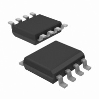
IC CTLR/MOSFET UNIV N-CH 8-SOIC
Manufacturer
International Rectifier
Datasheet
1.IR5001STRPBF.pdf
(12 pages)
Specifications of IR5001STRPBF
Package / Case
8-SOIC (3.9mm Width)
Mounting Type
Surface Mount
Current - Supply
500µA
Voltage - Supply
36 V ~ 75 V
Operating Temperature
0°C ~ 85°C
Applications
-48V Dist Power Systems, AdvancedTCA ® Systems
Number Of Outputs
1
Internal Switch(s)
No
Fet Type
N-Channel
Delay Time - On
27µs
Delay Time - Off
130ns
Operating Temperature (max)
125C
Operating Temperature (min)
-40C
Pin Count
8
Mounting
Surface Mount
Package Type
SOIC N
Screening Level
Automotive
Device Type
O-Ring Controller / MOSFET Driver
Input Delay
27µs
Output Delay
130ns
Driver Case Style
SOIC
No. Of Pins
8
Operating Temperature Range
0°C To +85°C
Rohs Compliant
Yes
Package
8-lead SOIC Narrow
Input Voltage
100V Max Continuous
Vline
36V to 75V 100V Max or 12Vreg
Offset Voltage (v)
-7.9mV min to 0V max
Turn-on Time (ns)
20
Turn-off Time (ns)
130
T Off Gate Drive
3A Peak
Junction Temperature
-40oC to 125oC
Special Ic
FetCheck Available
Lead Free Status / RoHS Status
Lead free / RoHS Compliant
Available stocks
Company
Part Number
Manufacturer
Quantity
Price

Part Number:
IR5001STRPBF
Manufacturer:
IR
Quantity:
20 000


ABSOLUTE MAXIMUM RATINGS
Vline Voltage
Vcc Voltage
Icc Current
INN, INP Voltage
FETch, FETst
FETst Sink Current
Junction Temperature
Storage Temperature Range
CAUTION:
1. Stresses above those listed in "Absolute Maximum Ratings" may cause permanent damage to the device. This
is a stress only rating and operation of the device at these or any other conditions above those indicated in the
operational section of this specification is not implied.
2. This device is ESD sensitive. Use of standard ESD handling precautions is required.
.
ELECTRICAL SPECIFICATIONS
Unless otherwise specified, these specifications apply over V
Gnd, C
apply to T
duty cycle pulse testing is used which keeps junction and case temperatures equal to the ambient temperature.
www.irf.com
Bias Section
Vline Bias Current
VCC output voltage
UVLO Section
UVLO ON Threshold Voltage
UVLO OFF Threshold Voltage
UVLO Hysteresis
Input Comparator Section
Input Offset Voltage (VINP-
VINN)
Input Hysteresis Voltage
(INN) Input Bias Current
(INP) Input Bias Current
L
=10nF at Vout; INP is connected to Gnd. Typical values refer to T
PARAMETERS
A
= 0°C to 85°C temperature range and are 100% production-tested at both temperature extremes. Low
Vcc(OFF)
SYMBOL
Vcc(out)
Vcc(ON)
Vhyst
I(INN)
I(INP)
Iline
Vos
Vcc increased until Vout switches
VINP=0V and VINN Ramping up,
0.3V, Vcc is decreased until
VOUT changes from HI to LO,
Vline=open, VINP=0; VINN= -
Vline=open, VINP=0, VINN=-
VINP=0,VINN ramping down,
Vout switches from HI to LO
from LO to HI, Note 2
VINP=0V, VINN=36V
VINN=0V, VINP=36V
Vline=100V, Note 1
TEST CONDITION
5mA
-5.0V to 100V (continuous)
-0.5V to 5.5V
10mA
-40°C to 125°C
-65°C to 150°C
-5.0V to 100V (continuous)
-0.5V to 15VDC
Figures 3 and 4
Vline=25V
Vline=36V
Vline=25V
line
Fig.3
0.3V
= 36V to 100V; Vcc is decoupled with 0.1uF to
A
=25°C. Minimum and maximum limits
IR5001S & (PbF)
0.14
10.2 12.5 14.1
MIN TYP MAX UNITS
-7.9 -4.0
0.2
1.2
8.0
5.6
1.6
0.2
0.2
13
0.3
0.5
1.7
9.6
7.2
2.3
0.5
0.5
31
0.75
10.7
0.5
2.2
8.8
2.8
0.9
0.9
44
0
mV
mA
mA
V
V
V
2
Related parts for IR5001STRPBF
Image
Part Number
Description
Manufacturer
Datasheet
Request
R

Part Number:
Description:
IC CTRLR/MOSFET UNIV N-CH 8SOIC
Manufacturer:
International Rectifier
Datasheet:

Part Number:
Description:
SCHOTTKY RECTIFIER
Manufacturer:
International Rectifier Corp.
Datasheet:
Part Number:
Description:
SCHOTTKY RECTIFIER
Manufacturer:
International Rectifier Corp.
Datasheet:
Part Number:
Description:
SCHOTTKY RECTIFIER
Manufacturer:
International Rectifier Corp.
Datasheet:
Part Number:
Description:
SCHOTTKY RECTIFIER
Manufacturer:
International Rectifier Corp.
Datasheet:
Part Number:
Description:
SCHOTTKY RECTIFIER
Manufacturer:
International Rectifier Corp.
Datasheet:
Part Number:
Description:
SCHOTTKY RECTIFIER
Manufacturer:
International Rectifier Corp.
Datasheet:
Part Number:
Description:
SCHOTTKY RECTIFIER
Manufacturer:
International Rectifier Corp.
Datasheet:
Part Number:
Description:
SCHOTTKY RECTIFIER
Manufacturer:
International Rectifier Corp.
Datasheet:
Part Number:
Description:
SCHOTTKY RECTIFIER
Manufacturer:
International Rectifier Corp.
Datasheet:
Part Number:
Description:
SCHOTTKY RECTIFIER
Manufacturer:
International Rectifier Corp.
Datasheet:
Part Number:
Description:
SCHOTTKY RECTIFIER
Manufacturer:
International Rectifier Corp.
Datasheet:
Part Number:
Description:
SCHOTTKY RECTIFIER
Manufacturer:
International Rectifier Corp.
Datasheet:
Part Number:
Description:
SCHOTTKY RECTIFIER
Manufacturer:
International Rectifier Corp.
Datasheet:
Part Number:
Description:
SCHOTTKY RECTIFIER
Manufacturer:
International Rectifier Corp.
Datasheet: