IRS26310DJPBF International Rectifier, IRS26310DJPBF Datasheet - Page 25
IRS26310DJPBF
Manufacturer Part Number
IRS26310DJPBF
Description
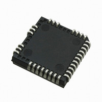
IC DRIVER BRIDGE 3-PHASE 44-PLCC
Manufacturer
International Rectifier
Datasheet
1.IRS26310DJTRPBF.pdf
(41 pages)
Specifications of IRS26310DJPBF
Configuration
3 Phase Bridge
Input Type
Non-Inverting
Delay Time
530ns
Current - Peak
200mA
Number Of Configurations
1
Number Of Outputs
3
High Side Voltage - Max (bootstrap)
600V
Voltage - Supply
12 V ~ 20 V
Operating Temperature
-40°C ~ 125°C
Mounting Type
Surface Mount
Package / Case
44-PLCC (32 Leads)
Peak Output Current
200mA
Input Delay
530ns
Output Delay
530ns
Supply Voltage Range
12V To 20V
Driver Case Style
LCC
No. Of Pins
44
Operating Temperature Range
-40°C To +125°C
Rohs Compliant
Yes
Device Type
High Side / Low Side
Family Hvic
General Purpose HVICs
Channels
6
Topology
Three Phase
Application
General Purpose / Motor Control / PDP
Voffset
600
Io+ (ma)
200
Io- (ma)
350
Shutdown / Reset
Yes
Separate Power And Logic Ground
Yes
Integrated Bootstrap Diode
Yes
Over Current Protection
Yes
Uvlo
Vcc / Vbs
Vbsuv+ / Vccuv+ Min (v)
10.4
Vbsuv+ / Vccuv+ Typ (v)
11.1
Vbsuv+ / Vccuv+ Max (v)
11.6
Vbsuv- / Vccuv- Min (v)
10.2
Vbsuv- / Vccuv- Typ (v)
10.9
Dt / Sdt Min (ns)
190
Dt / Sdt Typ (ns)
290
Dt / Sdt Max (ns)
420
T On Min (ns)
400
T On Typ (ns)
530
T On Max (ns)
750
T Off Min (ns)
400
T Off Typ (ns)
530
T Off Max (ns)
750
Fault Reporting
Yes
Package
44 Lead
Part Status
Active & Preferred
Special Features
DC Bus Sensing with Over Voltage Protection
Lead Free Status / RoHS Status
Lead free / RoHS Compliant
Available stocks
Company
Part Number
Manufacturer
Quantity
Price
Company:

Part Number:
IRS26310DJPBF
Manufacturer:
International Rectifier
Quantity:
10 000


Truth Table: Undervoltage lockout, ITRIP, and ENABLE
Table 4 provides the truth table for the IRS26310D. The first line shows that the UVLO for V
FAULT output has gone low and the gate drive outputs have been disabled. V
when V
DCbus OV has been tripped and that the zero vector mode has been activated.
The third case shows that the UVLO for V
disabled. After V
transition of HIN. The fourth case illustrates that the ITRIP trip threshold has been reached and that the gate drive
outputs have been disabled and a fault has been reported through the fault pin (When ITRIP< V
to High impedance after RCIN pin becomes greater than 8V). In the fifth case, the HVIC has received a command
through the EN input to shutdown; as a result, the gate drive outputs have been disabled. The last case shows the
normal operation of the HVIC (a shoot-through protection prevention logic prevent LO1,2,3 and HO1,2,3 for each
channel turn on simultaneously).
www.irf.com
DCbus OV
ITRIP fault
UVLO V
command
UVLO V
operation
Normal
CC
EN
is greater than V
CC
BS
BS
< V
VCC
15 V
15 V
15 V
15 V
15 V
exceeds the V
CCUV
Figure 16: Programming the DC bus over-voltage protection
CCUV
DCbus
>OVdc
<OVdc
<OVdc
<OVdc
<OVdc
sense
, the FAULT output returns to the high impedance state. The second case shows that
bus
bus
bus
bus
bus
---
BSUV
< V
DCbusSense
threshold , HO will stay low until the HVIC input receives a new or rising
VBS
15 V
15 V
15 V
---
---
BSUV
BS
has been tripped and that the high-side gate drive output has been
>V
ITRIP
Vss
0 V
0 V
0 V
---
---
ITRIP
25
5 V
5 V
0 V
5 V
EN
---
---
RCIN
High
High
High
High
High
Low
DCbus
Vx
R0
R1
FAULT
High Z
High Z
High Z
High Z
CCUV
0
0
IRS26310DJPbF
is not latched in this case and
© 2008 International Rectifier
LIN
LIN
LO
CC
0
1
0
0
has been tripped; the
ITRIP
FAULT returns
HIN
HO
0
0
0
0
0
Related parts for IRS26310DJPBF
Image
Part Number
Description
Manufacturer
Datasheet
Request
R

Part Number:
Description:
SCHOTTKY RECTIFIER
Manufacturer:
International Rectifier Corp.
Datasheet:
Part Number:
Description:
SCHOTTKY RECTIFIER
Manufacturer:
International Rectifier Corp.
Datasheet:
Part Number:
Description:
SCHOTTKY RECTIFIER
Manufacturer:
International Rectifier Corp.
Datasheet:
Part Number:
Description:
SCHOTTKY RECTIFIER
Manufacturer:
International Rectifier Corp.
Datasheet:
Part Number:
Description:
SCHOTTKY RECTIFIER
Manufacturer:
International Rectifier Corp.
Datasheet:
Part Number:
Description:
SCHOTTKY RECTIFIER
Manufacturer:
International Rectifier Corp.
Datasheet:
Part Number:
Description:
SCHOTTKY RECTIFIER
Manufacturer:
International Rectifier Corp.
Datasheet:
Part Number:
Description:
SCHOTTKY RECTIFIER
Manufacturer:
International Rectifier Corp.
Datasheet:
Part Number:
Description:
SCHOTTKY RECTIFIER
Manufacturer:
International Rectifier Corp.
Datasheet:
Part Number:
Description:
SCHOTTKY RECTIFIER
Manufacturer:
International Rectifier Corp.
Datasheet:
Part Number:
Description:
SCHOTTKY RECTIFIER
Manufacturer:
International Rectifier Corp.
Datasheet:
Part Number:
Description:
SCHOTTKY RECTIFIER
Manufacturer:
International Rectifier Corp.
Datasheet:
Part Number:
Description:
SCHOTTKY RECTIFIER
Manufacturer:
International Rectifier Corp.
Datasheet:
Part Number:
Description:
SCHOTTKY RECTIFIER
Manufacturer:
International Rectifier Corp.
Datasheet:
Part Number:
Description:
SCHOTTKY RECTIFIER
Manufacturer:
International Rectifier Corp.
Datasheet: