IRS26310DJPBF International Rectifier, IRS26310DJPBF Datasheet - Page 24
IRS26310DJPBF
Manufacturer Part Number
IRS26310DJPBF
Description
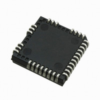
IC DRIVER BRIDGE 3-PHASE 44-PLCC
Manufacturer
International Rectifier
Datasheet
1.IRS26310DJTRPBF.pdf
(41 pages)
Specifications of IRS26310DJPBF
Configuration
3 Phase Bridge
Input Type
Non-Inverting
Delay Time
530ns
Current - Peak
200mA
Number Of Configurations
1
Number Of Outputs
3
High Side Voltage - Max (bootstrap)
600V
Voltage - Supply
12 V ~ 20 V
Operating Temperature
-40°C ~ 125°C
Mounting Type
Surface Mount
Package / Case
44-PLCC (32 Leads)
Peak Output Current
200mA
Input Delay
530ns
Output Delay
530ns
Supply Voltage Range
12V To 20V
Driver Case Style
LCC
No. Of Pins
44
Operating Temperature Range
-40°C To +125°C
Rohs Compliant
Yes
Device Type
High Side / Low Side
Family Hvic
General Purpose HVICs
Channels
6
Topology
Three Phase
Application
General Purpose / Motor Control / PDP
Voffset
600
Io+ (ma)
200
Io- (ma)
350
Shutdown / Reset
Yes
Separate Power And Logic Ground
Yes
Integrated Bootstrap Diode
Yes
Over Current Protection
Yes
Uvlo
Vcc / Vbs
Vbsuv+ / Vccuv+ Min (v)
10.4
Vbsuv+ / Vccuv+ Typ (v)
11.1
Vbsuv+ / Vccuv+ Max (v)
11.6
Vbsuv- / Vccuv- Min (v)
10.2
Vbsuv- / Vccuv- Typ (v)
10.9
Dt / Sdt Min (ns)
190
Dt / Sdt Typ (ns)
290
Dt / Sdt Max (ns)
420
T On Min (ns)
400
T On Typ (ns)
530
T On Max (ns)
750
T Off Min (ns)
400
T Off Typ (ns)
530
T Off Max (ns)
750
Fault Reporting
Yes
Package
44 Lead
Part Status
Active & Preferred
Special Features
DC Bus Sensing with Over Voltage Protection
Lead Free Status / RoHS Status
Lead free / RoHS Compliant
Available stocks
Company
Part Number
Manufacturer
Quantity
Price
Company:

Part Number:
IRS26310DJPBF
Manufacturer:
International Rectifier
Quantity:
10 000


DC bus Over-Voltage Protection
When driving permanent magnet ac motors there is a potential to regenerate some of the motor mechanical
energy back onto the dc bus. “Zero vector braking” prevents charging of the dc bus capacitor by shorting all
three motor terminals to a common rail to dissipate this mechanical energy in the motor windings. The dc bus
over-voltage protection feature on the IC initiates zero vector braking when the dc bus voltage goes above some
critical voltage level to prevent damage to dc bus components. Zero vector braking should only be used when
the motor winding inductance is sufficient to limit the motor short circuit current to a safe level. Dc bus protection
operates even when all PWM inputs are disabled so will protect the motor when operating in high speed field
weakening mode.
The IRS26310D ICs have a DCbusSense input pin to detect over-voltage events on the DC bus. Once the IC
detects an over-voltage event, zero vector mode braking is forced (all Low side output turn-on, all High side
output-turn-off) overriding the PWM signals coming from the controller. A fault is not reported on the FAULT pin
for this condition because the power inverter is still active. DC bus over-voltage protection is not latched and so
the zero vector mode is released when DCbusSense pin is lower than O
The level of voltage at which the over-voltage protection is initiated is determined by the resistor divider (i.e., R
R
designer will need to determine the maximum allowable level of DC bus voltage and select R
voltage at node V
www.irf.com
1
) connected to DCbusSense as shown in Figure 16, and the DCbusSense threshold (O
Figure 14: Programming over-temperature
X
reaches the over-voltage threshold (O
protection
O
VDCBUSVTH+
= R
24
VDCBUSVTH+
1
V
Figure 15: Using over-current protection and over-
DCBUS
/(R
).
0
+R
VDCBUSVTH-
1
)
temperature protection
.
IRS26310DJPbF
© 2008 International Rectifier
VDCBUSVTH+
0
and R
1
). The circuit
such that the
0
and
Related parts for IRS26310DJPBF
Image
Part Number
Description
Manufacturer
Datasheet
Request
R

Part Number:
Description:
SCHOTTKY RECTIFIER
Manufacturer:
International Rectifier Corp.
Datasheet:
Part Number:
Description:
SCHOTTKY RECTIFIER
Manufacturer:
International Rectifier Corp.
Datasheet:
Part Number:
Description:
SCHOTTKY RECTIFIER
Manufacturer:
International Rectifier Corp.
Datasheet:
Part Number:
Description:
SCHOTTKY RECTIFIER
Manufacturer:
International Rectifier Corp.
Datasheet:
Part Number:
Description:
SCHOTTKY RECTIFIER
Manufacturer:
International Rectifier Corp.
Datasheet:
Part Number:
Description:
SCHOTTKY RECTIFIER
Manufacturer:
International Rectifier Corp.
Datasheet:
Part Number:
Description:
SCHOTTKY RECTIFIER
Manufacturer:
International Rectifier Corp.
Datasheet:
Part Number:
Description:
SCHOTTKY RECTIFIER
Manufacturer:
International Rectifier Corp.
Datasheet:
Part Number:
Description:
SCHOTTKY RECTIFIER
Manufacturer:
International Rectifier Corp.
Datasheet:
Part Number:
Description:
SCHOTTKY RECTIFIER
Manufacturer:
International Rectifier Corp.
Datasheet:
Part Number:
Description:
SCHOTTKY RECTIFIER
Manufacturer:
International Rectifier Corp.
Datasheet:
Part Number:
Description:
SCHOTTKY RECTIFIER
Manufacturer:
International Rectifier Corp.
Datasheet:
Part Number:
Description:
SCHOTTKY RECTIFIER
Manufacturer:
International Rectifier Corp.
Datasheet:
Part Number:
Description:
SCHOTTKY RECTIFIER
Manufacturer:
International Rectifier Corp.
Datasheet:
Part Number:
Description:
SCHOTTKY RECTIFIER
Manufacturer:
International Rectifier Corp.
Datasheet: