IRS26310DJPBF International Rectifier, IRS26310DJPBF Datasheet - Page 22
IRS26310DJPBF
Manufacturer Part Number
IRS26310DJPBF
Description
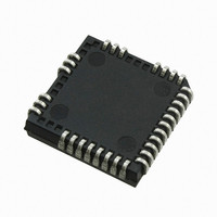
IC DRIVER BRIDGE 3-PHASE 44-PLCC
Manufacturer
International Rectifier
Datasheet
1.IRS26310DJTRPBF.pdf
(41 pages)
Specifications of IRS26310DJPBF
Configuration
3 Phase Bridge
Input Type
Non-Inverting
Delay Time
530ns
Current - Peak
200mA
Number Of Configurations
1
Number Of Outputs
3
High Side Voltage - Max (bootstrap)
600V
Voltage - Supply
12 V ~ 20 V
Operating Temperature
-40°C ~ 125°C
Mounting Type
Surface Mount
Package / Case
44-PLCC (32 Leads)
Peak Output Current
200mA
Input Delay
530ns
Output Delay
530ns
Supply Voltage Range
12V To 20V
Driver Case Style
LCC
No. Of Pins
44
Operating Temperature Range
-40°C To +125°C
Rohs Compliant
Yes
Device Type
High Side / Low Side
Family Hvic
General Purpose HVICs
Channels
6
Topology
Three Phase
Application
General Purpose / Motor Control / PDP
Voffset
600
Io+ (ma)
200
Io- (ma)
350
Shutdown / Reset
Yes
Separate Power And Logic Ground
Yes
Integrated Bootstrap Diode
Yes
Over Current Protection
Yes
Uvlo
Vcc / Vbs
Vbsuv+ / Vccuv+ Min (v)
10.4
Vbsuv+ / Vccuv+ Typ (v)
11.1
Vbsuv+ / Vccuv+ Max (v)
11.6
Vbsuv- / Vccuv- Min (v)
10.2
Vbsuv- / Vccuv- Typ (v)
10.9
Dt / Sdt Min (ns)
190
Dt / Sdt Typ (ns)
290
Dt / Sdt Max (ns)
420
T On Min (ns)
400
T On Typ (ns)
530
T On Max (ns)
750
T Off Min (ns)
400
T Off Typ (ns)
530
T Off Max (ns)
750
Fault Reporting
Yes
Package
44 Lead
Part Status
Active & Preferred
Special Features
DC Bus Sensing with Over Voltage Protection
Lead Free Status / RoHS Status
Lead free / RoHS Compliant
Available stocks
Company
Part Number
Manufacturer
Quantity
Price
Company:

Part Number:
IRS26310DJPBF
Manufacturer:
International Rectifier
Quantity:
10 000


Fault Reporting and Programmable Fault Clear Timer
The IRS26310D family provides an integrated fault reporting output and an adjustable fault clear timer. There are
two situations that would cause the HVIC to report a fault via the FAULT pin. The first is an undervoltage condition
of V
internally pulled to V
condition has been removed and the fault clear timer expires; once the fault clear timer expires, the voltage on the
FAULT pin will return to V
The length of the fault clear time period (t
capacitor where the time constant is set by R
occurred (UVLO or ITRIP), RCIN and FAULT are pulled to V
timer begins. Figure 12 shows that R
between the RCIN and V
The design guidelines for this network are shown in Table 3.
The length of the fault clear time period can be determined by using the formula below.
www.irf.com
CC
Figure 11: RCIN and FAULT pin waveforms
and the second is if the ITRIP pin recognizes a fault. Once the fault condition occurs, the FAULT pin is
SS
and the fault clear timer is activated. The fault output stays in the low state until the fault
SS
CC
pins.
.
t
RCIN
FLTCLR
is connected between the V
Table 3: Design guidelines
C
R
FLTCLR
= -(R
RCIN
RCIN
RCIN
v
and C
C
RCIN
) is determined by exponential charging characteristics of the
(t) = V
C
RCIN
22
RCIN
f
(1-e
)ln(1-V
. In Figure 11 where we see that a fault condition has
SS
0.5 MΩ to 2 MΩ
, and once the fault has been removed, the fault clear
-t/RC
Figure 12: Programming the fault clear timer
>> R
Ceramic
≤1 nF
)
RCIN,TH
ON,RCIN
/V
CC
CC
and the RCIN pin, while C
)
IRS26310DJPbF
© 2008 International Rectifier
RCIN
is placed
Related parts for IRS26310DJPBF
Image
Part Number
Description
Manufacturer
Datasheet
Request
R

Part Number:
Description:
SCHOTTKY RECTIFIER
Manufacturer:
International Rectifier Corp.
Datasheet:
Part Number:
Description:
SCHOTTKY RECTIFIER
Manufacturer:
International Rectifier Corp.
Datasheet:
Part Number:
Description:
SCHOTTKY RECTIFIER
Manufacturer:
International Rectifier Corp.
Datasheet:
Part Number:
Description:
SCHOTTKY RECTIFIER
Manufacturer:
International Rectifier Corp.
Datasheet:
Part Number:
Description:
SCHOTTKY RECTIFIER
Manufacturer:
International Rectifier Corp.
Datasheet:
Part Number:
Description:
SCHOTTKY RECTIFIER
Manufacturer:
International Rectifier Corp.
Datasheet:
Part Number:
Description:
SCHOTTKY RECTIFIER
Manufacturer:
International Rectifier Corp.
Datasheet:
Part Number:
Description:
SCHOTTKY RECTIFIER
Manufacturer:
International Rectifier Corp.
Datasheet:
Part Number:
Description:
SCHOTTKY RECTIFIER
Manufacturer:
International Rectifier Corp.
Datasheet:
Part Number:
Description:
SCHOTTKY RECTIFIER
Manufacturer:
International Rectifier Corp.
Datasheet:
Part Number:
Description:
SCHOTTKY RECTIFIER
Manufacturer:
International Rectifier Corp.
Datasheet:
Part Number:
Description:
SCHOTTKY RECTIFIER
Manufacturer:
International Rectifier Corp.
Datasheet:
Part Number:
Description:
SCHOTTKY RECTIFIER
Manufacturer:
International Rectifier Corp.
Datasheet:
Part Number:
Description:
SCHOTTKY RECTIFIER
Manufacturer:
International Rectifier Corp.
Datasheet:
Part Number:
Description:
SCHOTTKY RECTIFIER
Manufacturer:
International Rectifier Corp.
Datasheet: