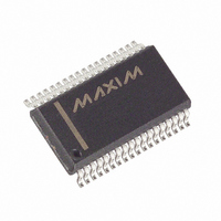
MAX5965BUAX+ Maxim Integrated Products, MAX5965BUAX+ Datasheet - Page 7

MAX5965BUAX+
Manufacturer Part Number
MAX5965BUAX+
Description
IC PSE CTRLR FOR POE 36SSOP
Manufacturer
Maxim Integrated Products
Type
Power Over Ethernet Controller (PoE)r
Datasheet
1.MAX5965AUAXT.pdf
(53 pages)
Specifications of MAX5965BUAX+
Applications
IP Phones, Power over LAN, Network Routers and Switches
Internal Switch(s)
No
Voltage - Supply
2.4 V ~ 3.6 V
Operating Temperature
0°C ~ 85°C
Mounting Type
Surface Mount
Package / Case
36-BSOP (0.300", 7.5mm Width)
Supply Voltage (max)
60 V
Supply Voltage (min)
32 V
Power Dissipation
1388.9 mW
Operating Temperature Range
0 C to + 85 C
Mounting Style
SMD/SMT
Lead Free Status / RoHS Status
Lead free / RoHS Compliant
ELECTRICAL CHARACTERISTICS (continued)
(V
V
wise.) (Note 2)
Note 2: Limits to T
Note 3: Default values. The charge/discharge currents are programmable through the serial interface (see the Register Map and
Note 4: Default values. The current-limit thresholds are programmed through the I
Note 5: Functional test is performed over thermal shutdown entering test mode.
Note 6: This is the default value. Threshold can be programmed through serial interface R23h[2:0].
Note 7: AC disconnect works only if (V
Note 8:
Note 9: R
Note 10: Default values. The startup and fault times can also be programmed through the I
Differential Nonlinearity
Gain Error
ADC Absolute Accuracy
TIMING CHARACTERISTICS (For 2-Wire Fast Mode)
Serial-Clock Frequency
Bus Free Time Between a
STOP and START Condition
Hold Time for a START
Condition
Low Period of the SCL Clock
High Period of the SCL Clock
Setup Time for a Repeated
START Condition (Sr)
Data Hold Time
Data in Setup Time
Rise Time of Both SDA and
SCL Signals, Receiving
Fall Time of SDA Transmitting
Setup Time for STOP Condition
Capacitive Load for Each Bus
Line
Pulse Width of Spike
Suppressed
AGND
AGND
High-Power, Quad, Monolithic, PSE Controllers
= +48V, V
= 32V to 60V, V
PARAMETER
Description section).
Map and Description section).
t
rent at DET_ during phase 1 and 2 of the detection.
and Description section).
DISC
D
= (V
can also be programmed through the serial interface (R16h) (see the Register Map and Description section).
DGND
OUT_2
A
_______________________________________________________________________________________
= -40°C are guaranteed by design.
EE
= +48V, V
- V
= 0V, V
OUT_1
)/(I
DD
DD
SYMBOL
DET_2
t
t
t
t
t
to V
HD, DAT
HD, STA
SU, DAT
SU, STO
SU, STA
t
= (V
t
DNL
f
t
HIGH
LOW
SCL
BUF
C
t
t
t
SP
R
F
B
DGND
DD
DGND
- I
- V
DET_1
= +3.3V, all voltages are referenced to V
DGND
V
+ 3.3V), T
SENSE_
). V
) ≥ 3V and DGND is connected to AGND.
OUT_1
= 300mV
A
, V
= +25°C. Currents are positive when entering the pin and negative other-
OUT_2
CONDITIONS
for Power over Ethernet
, I
DET_2
, and I
DET_1
2
C-compatible serial interface (see the Register
EE
represent the voltage at OUT_ and the cur-
, unless otherwise noted. Typical values are at
2
C serial interface (see the Register Map
0.1C
0.1C
20 +
20 +
MIN
295
100
100
1.2
0.6
1.2
0.6
0.6
0.6
B
B
TYP
300
0.2
MAX
305
400
300
300
300
400
1.5
50
3
UNITS
LSB
LSB
kHz
pF
µs
µs
µs
µs
µs
ns
ns
ns
ns
µs
ns
%
7


