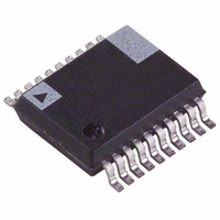
ADE7763ARSRL Analog Devices Inc, ADE7763ARSRL Datasheet - Page 42

ADE7763ARSRL
Manufacturer Part Number
ADE7763ARSRL
Description
IC ENERGY METER 1PHASE 20SSOP
Manufacturer
Analog Devices Inc
Datasheet
1.ADE7763ARSZRL.pdf
(56 pages)
Specifications of ADE7763ARSRL
Input Impedance
390 KOhm
Measurement Error
0.1%
Voltage - I/o High
2.4V
Voltage - I/o Low
0.8V
Current - Supply
3mA
Voltage - Supply
4.75 V ~ 5.25 V
Operating Temperature
-40°C ~ 85°C
Mounting Type
Surface Mount
Package / Case
20-SSOP (0.200", 5.30mm Width)
Meter Type
Single Phase
For Use With
EVAL-ADE7763ZEB - BOARD EVALUATION FOR ADE7763
Lead Free Status / RoHS Status
Contains lead / RoHS non-compliant
ADE7763
Voltage rms compensation is done after the square root.
where:
VRMS0 is the rms measurement without offset correction.
VRMS is linear from full-scale to full-scale/20.
To calibrate the offset, two VRMS measurements are required,
for example, at V
full-scale analog input range so that the smallest linear VRMS
reading is at V
where VRMS
correction for input V
If the range of the 12-bit, twos complement VRMSOS register is
not enough, use the voltage channel offset register, CH2OS, to
correct the VRMS offset.
Current rms compensation is performed before the square root:
where IRMS0 is the rms measurement without offset correction.
The current rms calculation is linear from full scale to full
scale/100.
To calibrate this offset, two IRMS measurements are required,
for example, at I
analog input range so that the smallest linear IRMS reading is at
I
MAX
Figure 77. Synchronizing VRMS and IRMS Readings with Zero Crossings
/50.
VRMS = VRMS0 + VRMSOS
VRMSOS =
IRMS
2
= IRMS0
1
nominal
SET INTERRUPT ENABLE FOR ZERO
and VRMS
RESET THE INTERRUPT STATUS
RESET THE INTERRUPT STATUS
CROSSING ADDR. 0x0A = 0x0010
b
nominal
READ REGISTER ADDR. 0x0C
READ REGISTER ADDR. 0x0C
V
and I
1
/10.
READ VRMS OR IRMS
×
2
ADDR. 0x17; 0x16
+ 32768 × IRMSOS
1
VRMS
and V
MAX
and V
INTERRUPT?
YES
2
/50. I
are rms register values without offset
V
nominal
2
2
2
, respectively.
−
−
MAX
V
V
/10. V
2
1
is set at half of the full-scale
×
NO
VRMS
nominal
1
is set at half of the
(60)
(61)
(62)
Rev. B | Page 42 of 56
where IRMS
correction for input I
Apparent Energy
App
meter gain adjustment and for setting the VAh/LSB
VADIV is similar to the CFDEN for the watt-hour calibration. It
should be the same across all meters and determines the VAh/LSB
constant. VAGAIN is used to calibrate individual meters.
Apparent energy gain calibration should be performed before
rms offset correction to make the most efficient use of the current
test points. Apparent energy gain and watt gain compensation
require testing at I
a lower test current. Apparent energy gain calibration can be
done simultaneously with the watt-hour gain calibration
using line cycle accumulation. In this case, LAENERGY and
LVAENERGY , the line cycle accumulation apparent energy
registers, are both read following t
inter
appa
The accumulation time is determined from Equation 3
the li
acco
VAENERGY register is
The VAh/LSB constant can be verified using this equation:
arent energy gain ca
rding to Equation 34. The VAh represente
IRMSOS =
VAENERGY =
rupt. Figure 78 sh
rent energy simu
VAGAIN = INT ⎜ ⎜
LVAE
INT
VAh = VAENERGY × VAh / LSB constant
VAENERGY
ne period can be determined from the peri
VAh
⎛
⎜
⎜
⎜
⎜
⎝
LSB
NERGY
VAh
LSB
1
and IRMS
constant
constant
32768
V
initial
IB(expected)
b
nominal
1
, while rms and watt offset correction requ
⎛
⎜
⎝
1
ltaneously.
⎛
⎜
⎝
and I
×
ows a flowchart for calibrating activ and
×
2
LVAENERGY
LVAENERGY
=
VADIV
libration is provided for both meter-to-
×
are rms register values without offset
×
I
VA
=
I
1
3600
2
2
1
B
, respectively.
×
×
IRMS
Accumulati
s/h
×
he line cycle accumulation
⎛ +
⎜
⎝
LVAENERGY
1
I
×
2
2
IB
IB
Accumulati
2
2
(
(
VAGAIN
expected
nominal
−
−
I
I
2
2
1
on
12
2
2
)
)
×
d by the
time
od register
−
IRMS
1
on
⎞
⎟
⎠
⎞
⎟
⎟
⎠
(
×
s
constant.
time
)
2
1
3600
12
2
3, and
⎞
⎟
⎟
⎠
( s
e
)
⎞
⎟
⎟
⎟
⎟
⎠
(63)
(64)
(65)
(66)
(67)
(68)
ire


