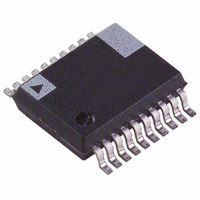
ADE7763ARSZ Analog Devices Inc, ADE7763ARSZ Datasheet - Page 2

ADE7763ARSZ
Manufacturer Part Number
ADE7763ARSZ
Description
IC ENERGY METERING 1PHASE 20SSOP
Manufacturer
Analog Devices Inc
Datasheet
1.ADE7763ARSZRL.pdf
(56 pages)
Specifications of ADE7763ARSZ
Input Impedance
390 KOhm
Measurement Error
0.1%
Voltage - I/o High
2.4V
Voltage - I/o Low
0.8V
Current - Supply
3mA
Voltage - Supply
4.75 V ~ 5.25 V
Operating Temperature
-40°C ~ 85°C
Mounting Type
Surface Mount
Package / Case
20-SSOP (0.200", 5.30mm Width)
Meter Type
Single Phase
Ic Function
Single-Phase Active And Apparent Energy Metering IC
Supply Voltage Range
4.75V To 5.25V
Operating Temperature Range
-40°C To +85°C
Digital Ic Case Style
SSOP
No. Of Pins
20
Lead Free Status / RoHS Status
Lead free / RoHS Compliant
For Use With
EVAL-ADE7763ZEB - BOARD EVALUATION FOR ADE7763
Lead Free Status / RoHS Status
Lead free / RoHS Compliant, Lead free / RoHS Compliant
Available stocks
Company
Part Number
Manufacturer
Quantity
Price
Part Number:
ADE7763ARSZ
Manufacturer:
ADI/亚德诺
Quantity:
20 000
Part Number:
ADE7763ARSZRL
Manufacturer:
ADI/亚德诺
Quantity:
20 000
ADE7763
TABLE OF CONTENTS
Specifications ..................................................................................... 3
Timing Characteristics ..................................................................... 4
Absolute Maximum Ratings ............................................................ 6
Terminology ...................................................................................... 7
Pin Configuration and Function Descriptions ............................. 8
Typical Performance Characteristics ........................................... 10
Theory of Operation ...................................................................... 13
REVISION HISTORY
8/09 —Rev. A to Rev. B
Changes to Zero Crossing Detection Section ............................. 15
Changes to Period Measurement Section ................................... 16
Changes to Channel 1 RMS Offset Calculation Section ........... 22
Changes to Channel 1 RMS Offset Compensation Section ...... 22
Changes to Figure 48 ...................................................................... 23
Changes to Channel 2 RMS Calculation Section ....................... 23
Changes to Table 11, Bit 15 Description ...................................... 51
Changes to Table 12, Bit 4 Description ........................................ 52
ESD Caution .................................................................................. 6
Analog Inputs .............................................................................. 13
di/dt Current Sensor and Digital Integrator ........................... 14
Zero-Crossing Detection ........................................................... 15
Period Measurement .................................................................. 16
Power Supply Monitor ............................................................... 16
Line Voltage Sag Detection ....................................................... 17
Peak Detection ............................................................................ 17
Interrupts ..................................................................................... 18
Temperature Measurement ....................................................... 19
Analog-to-Digital Conversion .................................................. 19
Channel 1 ADC ........................................................................... 20
Channel 2 ADC ........................................................................... 22
Phase Compensation .................................................................. 24
Active Power Calculation .......................................................... 25
Energy Calculation ..................................................................... 26
Rev. B | Page 2 of 56
Registers ........................................................................................... 47
Register Descriptions ..................................................................... 50
Outline Dimensions ....................................................................... 54
10/04—Data Sheet Changed from Rev. 0 to Rev. A
Changes to Period Measurement Section .................................. 16
Changes to Temperature Measurement Section ........................ 19
Change to Energy-to-Frequency Conversion Section .............. 28
Update to Figure 61 ....................................................................... 29
Change to Apparent Energy Calculation Section...................... 32
Change to Description of AEHF and VAEHF Bits ................... 52
Changes to Ordering Guide ......................................................... 54
4/04—Revision 0: Initial Version
Power Offset Calibration ........................................................... 28
Energy-to-Frequency Conversion ........................................... 28
Line Cycle Energy Accumulation Mode ................................. 30
Positive-Only Accumulation Mode ......................................... 30
No-Load Threshold .................................................................... 30
Apparent Power Calculation ..................................................... 31
Apparent Energy Calculation ................................................... 32
Line Apparent Energy Accumulation ...................................... 33
Energies Scaling .......................................................................... 34
Calibrating an Energy Meter .................................................... 34
CLKIN Frequency ...................................................................... 43
Suspending Functionality.......................................................... 44
Checksum Register..................................................................... 44
Serial Interface ............................................................................ 44
Communication Register .......................................................... 50
Mode Register (0x09) ................................................................. 50
Interrupt Status Register (0x0B), Reset Interrupt Status
Register (0x0C), Interrupt Enable Register (0x0A) ............... 52
CH1OS Register (0x0D) ............................................................ 53
Ordering Guide .......................................................................... 54


