STPM11ATR STMicroelectronics, STPM11ATR Datasheet - Page 24

STPM11ATR
Manufacturer Part Number
STPM11ATR
Description
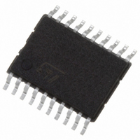
IC ENERGY METER 1 PHASE 20TSSOP
Manufacturer
STMicroelectronics
Datasheet
1.STPM13ATR.pdf
(46 pages)
Specifications of STPM11ATR
Input Impedance
100 KOhm
Measurement Error
0.1%
Voltage - I/o High
1.5V
Voltage - I/o Low
0.8V
Current - Supply
4.7mA
Voltage - Supply
3 V ~ 5.5 V
Operating Temperature
-40°C ~ 85°C
Mounting Type
Surface Mount
Package / Case
20-TSSOP
Meter Type
Single Phase
Output Voltage
+/- 0.4 V
Output Current
150 mA
Input Voltage
3 V to 5.5 V
Operating Temperature Range
- 40 C to + 85 C
Mounting Style
SMD/SMT
Lead Free Status / RoHS Status
Lead free / RoHS Compliant
Other names
497-5984-2
Theory of operation
Figure 18. Different oscillator circuits (a); (b); (c)
7.12
7.13
24/46
STPM12/14 with quartz
Resetting the STPM1x
The STPM1x has no reset pin. The device is automatically reset by the POR circuit when
the V
the analog part are kept off for about 30 ms and all blocks of the digital part are held in a
reset state for about 125 ms after a reset condition.
Resetting the STPM1x causes all the functional modules of STPM1x to be cleared including
the OTP shadow latches (see 7.15 for OTP shadow latches description)
Energy to frequency conversion
The STPM1x provides energy to frequency conversion both for calibration and energy
readout purposes. In fact, one convenient way to verify the meter calibration is to provide a
pulse train signal with 50% duty cycle whose frequency signal is proportional to the active
energy under steady load conditions. It is convenient to have high frequency pulses during
calibration phase and low frequency for readout purposes; STPM1x supports both cases.
Let's suppose to choose a certain number of pulses on the LED pin (high frequency) that will
corresponds to 1 kWh. We will name this value as P.
The Active Energy frequency-based signal is available in the LED pin. The LED is driven
from internal signal AW (Active Energy) whose frequency is proportional to the active
energy. The desired P is achieved acting on the digital calibrators during the calibration
procedure.
The APL configuration bit changes the internal divider that provides the signal on the LED
pin according to
provide low frequency pulses for readout purposes. The division factor is set according to
KMOT configuration bits. In this case the pulses will have a fixed width of 31.25 ms.
CC
crosses the 2.5 V value. When the reset occurs, all clocks and both DC buffers in
Table
13, setting APL=1 the number of pulses are reduced in order to
Doc ID 13167 Rev 7
STPM11/13
STPM11, STPM12, STPM13, STPM14
STPM12/14 with external source


