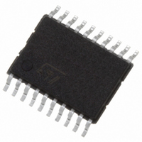
STPM11ATR STMicroelectronics, STPM11ATR Datasheet - Page 15

STPM11ATR
Manufacturer Part Number
STPM11ATR
Description
IC ENERGY METER 1 PHASE 20TSSOP
Manufacturer
STMicroelectronics
Datasheet
1.STPM13ATR.pdf
(46 pages)
Specifications of STPM11ATR
Input Impedance
100 KOhm
Measurement Error
0.1%
Voltage - I/o High
1.5V
Voltage - I/o Low
0.8V
Current - Supply
4.7mA
Voltage - Supply
3 V ~ 5.5 V
Operating Temperature
-40°C ~ 85°C
Mounting Type
Surface Mount
Package / Case
20-TSSOP
Meter Type
Single Phase
Output Voltage
+/- 0.4 V
Output Current
150 mA
Input Voltage
3 V to 5.5 V
Operating Temperature Range
- 40 C to + 85 C
Mounting Style
SMD/SMT
Lead Free Status / RoHS Status
Lead free / RoHS Compliant
Other names
497-5984-2
STPM11, STPM12, STPM13, STPM14
7
7.1
7.2
Table 7.
Gain
Theory of operation
General operation
The STPM1X is able to perform active energy measurement (wide band or fundamental) in
single-phase energy meter systems.
Due to the proprietary energy computation algorithm, STPM1X active energy is not affected
by any ripple at twice the line frequency. The calibration is very easy and fast allowing
calibration in only one point over the whole current range which allows saving time during
the calibration phase of the meter. The calibration parameters are permanently stored in the
OTP (one time programmable) cells, preventing calibration tampering.
Several functions are programmable using internal configuration bits accessible through the
configuration interface. The most important configuration bits are two configuration bits
called PST that allow the selection of the sensor and the gain of the input amplifiers.
The STPM1X is able to directly drive a stepper motor with the MOP and MON pins, and
provides information on tamper, no-load and negative power.
Two kinds of active energy can be selected to be brought to the LED pin: the total active
energy that includes all harmonic content up to 50
to the 1
energy.
Analog inputs
Input amplifiers
The STPM1X has one fully differential voltage input channel and one (STPM11/12) or two
(STPM13/14) fully differential current input channels.
differential input voltage for the voltage channel is ± 0.3 V.
In STPM13/14, the two current channels are multiplexed (see tamper section for details) to
provide a single input to a preamplifier with a gain of 4. The output of this preamplifier is
connected to the input of a programmable gain amplifier (PGA) with possible gain selections
of 2, 4, 6, 8. The total gain of the current channels will be then 8, 16, 24, 32. The gain
selections are made by writing to the gain configuration bits PST and it can be different for
the two current channels. The maximum differential input voltage is dependent on the
selected gain according to the
Voltage channel
4
The voltage channel consists of a differential amplifier with a gain of 4. The maximum
Voltage channels
st
harmonic. This last energy value is obtained by filtering the wide band active
Max input voltage (V)
±0.30
Doc ID 13167 Rev 7
Table
7:
th
harmonic and the active energy limited
Gain
16X
24X
32X
8X
Current channels
Max input voltage (V)
Theory of operation
±0.075
±0.035
±0.15
±0.05
15/46


