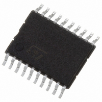
STPM11ATR STMicroelectronics, STPM11ATR Datasheet - Page 18

STPM11ATR
Manufacturer Part Number
STPM11ATR
Description
IC ENERGY METER 1 PHASE 20TSSOP
Manufacturer
STMicroelectronics
Datasheet
1.STPM13ATR.pdf
(46 pages)
Specifications of STPM11ATR
Input Impedance
100 KOhm
Measurement Error
0.1%
Voltage - I/o High
1.5V
Voltage - I/o Low
0.8V
Current - Supply
4.7mA
Voltage - Supply
3 V ~ 5.5 V
Operating Temperature
-40°C ~ 85°C
Mounting Type
Surface Mount
Package / Case
20-TSSOP
Meter Type
Single Phase
Output Voltage
+/- 0.4 V
Output Current
150 mA
Input Voltage
3 V to 5.5 V
Operating Temperature Range
- 40 C to + 85 C
Mounting Style
SMD/SMT
Lead Free Status / RoHS Status
Lead free / RoHS Compliant
Other names
497-5984-2
Theory of operation
Table 10.
7.5
18/46
Rogowsky
CT-Shunt
Equation 1
(CT/Shunt)
Equation 2
(Rogowsky)
Where K
The BFR flag is cleared when the V
error is set, the computation of power is suspended and MOP, MON and LED will be held
low.
RMS voltage check
Single wire meter mode (STPM13/14 with Rogowsky coil
sensor)
STPM1X supports the single wire meter (SWM) operation when working with Rogowsky
Coil current sensors. In SWM mode there is no available voltage information in the voltage
channel. It is possible that someone has disconnected one wire (live or neutral) of the meter
for tampering purposes or in case the line voltage is very stable, it is possible to use a
predefined value for computing the energy without sensing it.
In order to enable the SWM mode, the STPM1X must be configured with PST values of 0 or
1. In this way, if the BFR error is detected, STPM1X enters in SWM. If BFR is cleared, the
energy calculation is performed normally. When BFR is set (no voltage information is
available), the energy computation is carried out using a nominal voltage value according to
the NOM configuration bits.
Since there is no information on the phase shift between voltage and current, the apparent
rather than active power is used for tamper and energy computation. The calculated
apparent energy will be the product between I
V
V
STPM1X and K
V
V
RMS
RMS
IRMS
IRMS
=VPK*K
−
−
that can be calculated as follows:
BFR
BFR
V
is the voltage calibrator value ranging from 0.875 to 1.000.
=
=
6703
6687
NOM
NOM
64
64
, where VPK represents the maximum line voltage reading of the
⋅
⋅
K
K
is a coefficient that changes according to
V
V
0.009571/Kv
0.0078/Kv
BFR-on
Doc ID 13167 Rev 7
IRMS
value goes above twice V
RMS
(effectively measured) and an equivalent
STPM11, STPM12, STPM13, STPM14
Table
0.019142/Kv
0.0156/Kv
IRMS-BFR
BFR-off
11:
. When the BFR


