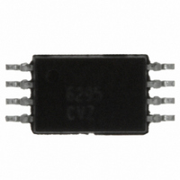
ISL6295CVZ Intersil, ISL6295CVZ Datasheet - Page 7

ISL6295CVZ
Manufacturer Part Number
ISL6295CVZ
Description
IC FUEL GAUGE LOW VOLTAGE8-TSSOP
Manufacturer
Intersil
Datasheet
1.ISL6295CVZ.pdf
(25 pages)
Specifications of ISL6295CVZ
Function
Fuel, Gas Gauge/Monitor
Battery Type
Lithium-Ion (Li-Ion), Lithium-Polymer (Li-Pol)
Voltage - Supply
2.8 V ~ 7 V
Operating Temperature
-20°C ~ 85°C
Mounting Type
Surface Mount
Package / Case
8-TSSOP
Battery Management Function
Fuel Gauge
Supply Voltage Range
2.8V To 7V
Interface Type
2-Wire, Serial, I2C
Battery Ic Case Style
TSSOP
No. Of Pins
8
Rohs Compliant
Yes
Lead Free Status / RoHS Status
Lead free / RoHS Compliant
Available stocks
Company
Part Number
Manufacturer
Quantity
Price
Company:
Part Number:
ISL6295CVZ
Manufacturer:
Intersil
Quantity:
40
Company:
Part Number:
ISL6295CVZ
Manufacturer:
INTERSIL
Quantity:
17
Part Number:
ISL6295CVZ
Manufacturer:
INTERSIL
Quantity:
20 000
Ictrl programming in a typical application is as follows:
VOLTAGE MEASUREMENTS
An analog multiplexer and divider network is provided to
support measurement of battery pack voltages. The A/D
control registers VPctrl and GPADctrl are used to specify the
measurement to be made. In typical applications, voltage
measurement a pack level is done using the 340mV
reference and a 10-bit magnitude resolution.
The value of the LSB in a pack voltage measurement using
the 340mV reference voltage and 15 bit resolution is given
by the formula:
V
VPctrl programming in a typical application is as follows:
The input source fields for the VPctrl, and GPADctrl registers
must be programmed to select the pack voltage VP and the
general purpose A/D input voltage GPAD in order for these
registers to control their intended measurements.
The measurable input range for VP is from 2.8V to 7V. The
measurable input range for GPAD is from 0V to 6.2V.
TEMPERATURE MEASUREMENTS
A/D input channels are provided for temperature
measurement using either the internal temperature sensor
or an external thermistor.
Defined within the ITctrl register is settings for the reference
utilized and the resolution desired for measurement of
temperature using the internal temperature sensor. Due to
the voltage output range of the temperature sensor, the
340mV reference must be selected.
The temperature measurement given by the internal
temperature sensor is derived using the following equation:
IT(°C) = (ITres – 22421)/78.95 °C
Typically, 10-bit resolution is selected, which results in the
following temperature measurement resolution:
IT(Δ) = 0.405°C/LSB
BIT(s)
BIT(s)
PACK
6-4
2-0
6-4
2-0
7
3
7
3
LSB = 10.2V/2
NAME VALUE
NAME
Res
Ref
Sel
Res
En
Ref
EN
Sel
VALUE
010
011
000
1
1
111
1
0
15
Enables A/D conversion
Selects 10-bit resolution
Selects 340mV Reference
Selects Vpack (VP) as ADC input
= 311.3µV
ENABLES A/D CONVERSION
Selects 15-bit resolution
Selects 170mV Reference
Selects VSR as ADC input
7
FUNCTION
FUNCTION
ISL6295
For temperature measurement using an external sensor, the
NTC pin sources a current of 12.5µA. For proper operation,
an industry standard 10kΩ at 25°C negative temperature
coefficient (NTC) device with a proper resistance range
should be connected between the NTC and GND pins. The
NTC reference output is only enabled during an external
temperature measurement in order to minimize power
consumption.
Defined within the ETctrl register are settings for the
reference utilized and the resolution desired for
measurement of temperature using the external temperature
sensor. The accuracy of temperature measurement using
the external thermistor is directly determined by the
characteristic of the NTC device used. It is suggested that
temperature measurements be thoroughly characterized to
extract the best-fit equation for temperature determination.
Internal to the ISL6295, a voltage inverter is provided to
translate the NTC voltage to a PTC voltage so that a larger
A/D conversion result would correspond to a higher
temperature reading. The actual voltage presented to the
ADC is as follows:
V
where V
For typical NTC devices, the 340mV reference should be
used to cover the expected operational temperature range of
the battery pack. For a NTC with a 10kΩ resistance at 25°C,
the voltage at the NTC pin will be 125mV, which corresponds
to an ADC input of (340-125)mV = 215mV. The expected
conversion result would be 215/340 * 2
OFFSET COMPENSATION
The host software can perform offset compensation by using
an offset measurement value read from the ISL6295. When
the offset calibration is enabled within the OFFSctrl register,
the converter input is internally shorted to ground and an A/D
conversion is performed at the specified resolution. The
offset value is stored in the OFFSres register.
ACCUMULATION/TIMING
The ISL6295 incorporates four 32-bit accumulators and four
32-bit elapsed time counters. The Discharge Current
Accumulator (DCA) and the Charge Current Accumulator
(CCA) are intended to record discharge and charge capacity
values. The Discharge Time Counter (DTC) and the Charge
Time Counter (CTC) are intended to maintain the total
discharge time and charge time. Accumulated charge and
discharge values can be used to determine state of charge
of the battery as well as cycle count information. With
information provided by the elapsed time counters, average
charge and discharge currents over an extended period of
time can be calculated.
Each of the four 32-bit accumulator registers is assigned a
fixed “source” A/D result register. When the accumulator is
ADC
= V
REF
REF
is the reference voltage selected.
- V
NTC
15
= 20721.
February 8, 2011
FN9074.2


