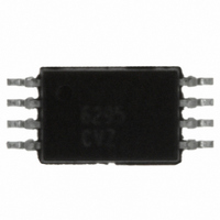
ISL6295CVZ Intersil, ISL6295CVZ Datasheet - Page 3

ISL6295CVZ
Manufacturer Part Number
ISL6295CVZ
Description
IC FUEL GAUGE LOW VOLTAGE8-TSSOP
Manufacturer
Intersil
Datasheet
1.ISL6295CVZ.pdf
(25 pages)
Specifications of ISL6295CVZ
Function
Fuel, Gas Gauge/Monitor
Battery Type
Lithium-Ion (Li-Ion), Lithium-Polymer (Li-Pol)
Voltage - Supply
2.8 V ~ 7 V
Operating Temperature
-20°C ~ 85°C
Mounting Type
Surface Mount
Package / Case
8-TSSOP
Battery Management Function
Fuel Gauge
Supply Voltage Range
2.8V To 7V
Interface Type
2-Wire, Serial, I2C
Battery Ic Case Style
TSSOP
No. Of Pins
8
Rohs Compliant
Yes
Lead Free Status / RoHS Status
Lead free / RoHS Compliant
Available stocks
Company
Part Number
Manufacturer
Quantity
Price
Company:
Part Number:
ISL6295CVZ
Manufacturer:
Intersil
Quantity:
40
Company:
Part Number:
ISL6295CVZ
Manufacturer:
INTERSIL
Quantity:
17
Part Number:
ISL6295CVZ
Manufacturer:
INTERSIL
Quantity:
20 000
Electrical Specifications
NOTES:
A/D CONVERTER CHARACTERISTICS (T
A/D Converter Resolution
A/D Conversion Measurement Time
A/D Converter Input Voltage Range
(internal)
Internal Temperature Accuracy
Calibrated Voltage Measurement
Gain Error
Calibrated Current Measurement
Gain Error (with ideal ZTC current
sense resistor)
Calibrated Temperature Measurement
Gain Error (internal sensor)
Calibrated ADC Offset Error
Integrated Nonlinearity Error
1. Does not include current consumption due to external loading on pins. No EEPROM access.
2. Sample mode current is specified during an A/D inactive cycle. Sample mode average current can be calculated using the formula: Average
3. Guaranteed by characterization or correlation to other test.
4. The max calibrated gain and offset errors are based on a 15-bit calibration procedure to generate the calibration factors. These calibration
5. Voltage is internal at A/D converter inputs. VSR is measured directly. VP and GPAD inputs are measured using internal level-translation circuitry
Sample Mode Supply Current = (IDDRUN + (n-1)*IDDINS)/Ns; where Ns is the programmed sample rate.
factors are then applied to correct the ADC results.
that scales the input voltage range appropriately for the converter.
PARAMETER
3
Typical Values Are Tested at V
Are Guaranteed Under the Recommended Operating Conditions., Unless Otherwise Noted. (Continued)
E VOFFSET
SYMBOL
E VGAIN
E TEMP
E IGAIN
A
V ADIN
tconv
T
E INL
ACC
= -20°C to +85°C; V
N
Magnitude only (Note 5)
N-bit + sign
Differential
Single-Ended
Max deviation over supply voltage
and temperature range (assumed
ideal under the calibration condition)
Max deviation over supply voltage
and temperature range (assumed
ideal under the calibration condition)
Max deviation over supply voltage
and temperature range (assumed
ideal under the calibration condition)
Max deviation over supply voltage
and temperature range (assumed
ideal under the calibration condition)
V
V
REF
REF
P
= 170mV
= 340mV
TEST CONDITIONS
ISL6295
P
= 5V and ambient temperature is at 25°C, All Maximum and Minimum Values
= 3.0V to 7.0V, Note 3, 4)
-152
MIN
-3
8
0
2
(N+1)
TYP
/f
A/D
+152
MAX
0.60
0.50
0.60
0.30
0.15
0.01
309
15
3
February 8, 2011
UNITS
FN9074.2
bits
mV
mV
°K
%
%
%
%
%
%
s


