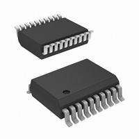
ISL55142IVZ Intersil, ISL55142IVZ Datasheet - Page 4

ISL55142IVZ
Manufacturer Part Number
ISL55142IVZ
Description
IC COMP CMOS HS 18V 20-TSSOP
Manufacturer
Intersil
Type
Windowr
Datasheet
1.ISL55141IVZ.pdf
(14 pages)
Specifications of ISL55142IVZ
Number Of Elements
2
Voltage - Supply
10 V ~ 18 V
Mounting Type
Surface Mount
Package / Case
20-TSSOP
Lead Free Status / RoHS Status
Lead free / RoHS Compliant
Electrical Specifications
Absolute Maximum Ratings
V
Input Voltages
Output Voltage
CAUTION: Do not operate at or near the maximum ratings listed for extended periods of time. Exposure to such conditions may adversely impact product reliability and
result in failures not covered by warranty.
NOTES:
Recommended Operating Conditions
DC CHARACTERISTICS
Input Offset Voltage
Input Bias Current
Power-down Current
Power-down Time (Note 11)
Power-up Time (Note 11)
TIMING CHARACTERISTICS
Propagation Delay
Rise Time (Note 11)
Fall Time (Note 11)
Propagation Delay Mismatch
Maximum Operating Frequency
Min Pulse Width
COMPARATOR INPUT
Input Current
Device Power
Comparator Output High Rail
Comparator Output Low Rail
Common Mode Input Voltage Range
Ambient Temperature
Junction Temperature
4. θ
5. For θ
6. θ
7. For θ
8. Device temperature is closely tied to data-rates, driver loads and overall pin activity. Review “Power Dissipation Considerations” on page 6 for
CC
PD, CV
Q
. . . . . . . . . . . . . . . . . . . . . . . . . . . . . (V
AX
Tech Brief TB379.
more information.
to V
JA
JA
, Q
is measured with the component mounted on a high effective thermal conductivity test board in free air. See Tech Brief TB379 for details.
is measured in free air with the component mounted on a high effective thermal conductivity test board with “direct attach” features. See
EE
JC
JC
AX
BX
, the “case temp” location is taken at the package top center.
, the “case temp” location is the center of the exposed metal pad on the package underside.
, CV
. . . . . . . . . . . . . . . . . . . . . . . . . . . . . . . . . -0.5V to 19V
. . . . . . . . . . . . . . . . . . . . . (V
PARAMETER
PARAMETER
BX
, V
INPX
, V
OH
, V
4
Test Conditions: V
otherwise specified.
OL
OL
EE
SYMBOL
F
t
I
WIDR
V
Δt
MAXR
-0.5V) to (V
BIAS
I
t
t
-0.5V) to (V
t
I
PD
PD
PU
pd
OS
t
IN
t
r
f
pd
ISL55141, ISL55142, ISL55143
SYMBOL
V
CC
CC
V
V
V
CV
V
PD = V
Symmetry 50%
V
T
T
OH
CM
OL
INPX
INPX
-V
A
J
= 12V, V
OH
CC
AX
EE
= CV
+0.5V)
+0.5V)
- CV
= V
CC
TEST CONDITIONS
CC
EE
BX
(A/B)X
or V
= -3V, V
= 1.5V
= ±5V
EE
V
V
OH
EE
MIN
V
Thermal Information
Thermal Resistance (Typical, Note 8)
Maximum Junction Temperature (Plastic Plackage) . .
Maximum Storage Temperature Range . . . . . . . . . . . -65°C to 150°C
Pb-Free Reflow Profile. . . . . . . . . . . . . . . . . . . . . . . . .see link below
EE
-40
10
EE
+0.5
16 Ld QFN Package (Notes 6, 7). . . . .
14 Ld TSSOP Package (Notes 4, 5) . .
20 Ld QFN Package (Notes 6, 7). . . . .
20 Ld TSSOP Package (Notes 4, 5) . .
36 Ld TQFN Package (Notes 6, 7). . . .
http://www.intersil.com/pbfree/Pb-FreeReflow.asp
+1
= 5V, V
OL
= 0V, PD = V
TYP
15
27
(Note 13)
-100
MIN
-50
4.0
EE
, C
LOAD
TYP
9.5
1.4
1.5
0.5
7.7
10
10
15
65
8
0
V
V
V
CC
MAX
+125
EE
+85
CC
= 15pF
18
-0.5
+6
-5
(Note 13)
θ
JA
MAX
,
100
T
50
25
25
15
2
100
(°C/W)
A
40
31
76
29
= 25°C, unless
UNITS
θ
March 1, 2011
°C
°C
JC
UNITS
V
V
V
V
MHz
mV
0.75
150°
nA
µA
nA
µs
µs
ns
ns
ns
ns
ns
FN6230.2
1.4
(°C/W)
31
25
3


