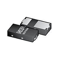
PMEG2010EPK NXP Semiconductors, PMEG2010EPK Datasheet - Page 8

PMEG2010EPK
Manufacturer Part Number
PMEG2010EPK
Description
Planar Maximum Efficiency General Application (MEGA) Schottky barrier rectifier with an integrated guard ring for stress protection, encapsulated in a leadless ultra small SOD1608 Surface-Mounted Device (SMD) plastic package with visible and solderab
Manufacturer
NXP Semiconductors
Datasheet
1.PMEG2010EPK.pdf
(13 pages)
NXP Semiconductors
8. Test information
PMEG2010EPK
Product data sheet
Fig 13. Average forward current as a function of solder point temperature; typical values
Fig 14. Duty cycle definition
T
(1) δ = 1 (DC)
(2) δ = 0.5; f = 20 kHz
(3) δ = 0.2; f = 20 kHz
(4) δ = 0.1; f = 20 kHz
j
= 150 °C
8.1 Quality information
The current ratings for the typical waveforms as shown in figures 10, 11,
calculated according to the equations: I
I
This product has been qualified in accordance with the Automotive Electronics Council
(AEC) standard Q101 - Stress test qualification for discrete semiconductors, and is
suitable for use in automotive applications.
RMS
= I
F(AV)
I
F(AV)
(A)
1.5
1.0
0.5
0.0
at DC, and I
0
All information provided in this document is subject to legal disclaimers.
(1)
(2)
(3)
(4)
P
25
Rev. 1 — 20 January 2012
RMS
50
t
p
= I
75
t
cy
M
× √δ with I
duty cycle δ =
100
20 V, 1 A low VF MEGA Schottky barrier rectifier
F(AV)
006aac658
125
T
RMS
= I
t
sp
t
t
006aac963
cy
150
p
(°C)
M
defined as RMS current.
× δ with I
175
PMEG2010EPK
M
defined as peak current,
© NXP B.V. 2012. All rights reserved.
12
and
13
are
8 of 13


