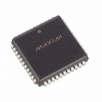
DS2151QB Maxim Integrated Products, DS2151QB Datasheet - Page 37

DS2151QB
Manufacturer Part Number
DS2151QB
Description
IC TXRX T1 1-CHIP 5V LP 44-PLCC
Manufacturer
Maxim Integrated Products
Datasheet
1.DS2151QB.pdf
(60 pages)
Specifications of DS2151QB
Function
Single-Chip Transceiver
Interface
T1
Number Of Circuits
1
Voltage - Supply
4.75 V ~ 5.25 V
Current - Supply
65mA
Operating Temperature
0°C ~ 70°C
Mounting Type
Surface Mount
Package / Case
44-LCC, 44-PLCC
Includes
Alarm Detector and Generator, CSU Loop Codes Generator and Detector, DSX-1 and CSU Line Build-Outs Generator
Lead Free Status / RoHS Status
Contains lead / RoHS non-compliant
Power (watts)
-
Available stocks
Company
Part Number
Manufacturer
Quantity
Price
Part Number:
DS2151QB
Manufacturer:
DALLAS
Quantity:
20 000
Company:
Part Number:
DS2151QB+
Manufacturer:
Maxim Integrated Products
Quantity:
135
Company:
Part Number:
DS2151QB+
Manufacturer:
VISHAY
Quantity:
6 509
DS2151Q
11 ELASTIC STORES OPERATION
The DS2151Q has two on-board two-frame (386 bits) elastic stores. These elastic stores have two main
purposes. First, they can be used to rate-convert the T1 data stream to 2.048Mbps (or a multiple of
2.048Mbps), which is the E1 rate. Secondly, they can be used to absorb the differences in frequency and
phase between the T1 data stream and an asynchronous (i.e., not frequency locked) backplane clock. Both
elastic stores contain full controlled slip capability, which is necessary for this second purpose. The
receive side elastic store can be enabled via CCR1.2 and the transmit side elastic store is enabled via
CCR1.7. The elastic stores can be forced to a known depth via the Elastic Store Reset bit (CCR3.6).
11.1 Receive Side
If the receive side elastic store is enabled (CCR1.2 = 1), then the user must provide either a 1.544MHz
(CCR1.3 = 0) or 2.048MHz (CCR1.3 = 1) clock at the SYSCLK pin. The user has the option of either
providing a frame sync at the RSYNC pin (RCR2.3 = 1) or having the RSYNC pin provide a pulse on
frame boundaries (RCR2.3 = 0). If the user wishes to obtain pulses at the frame boundary, then RCR2.4
must be set to 0 and if the user wishes to have pulses occur at the multiframe boundary, then RCR2.4
must be set to 1. If the user selects to apply a 2.048 MHz clock to the SYSCLK pin, then the data output
at RSER will be forced to all 1s every fourth channel and the F-bit will be deleted. Hence, channels 1, 5,
9, 13, 17, 21, 25, and 29 (time slots 0, 4, 8, 12, 16, 20, 24, and 28) will be forced to a 1.
Also, in 2.048MHz applications, the RCHBLK output will be forced high during the same channels as the
RSER pin. See Section
16
for more details. This is useful in T1 to CEPT (E1) conversion applications. If
the 386-bit elastic buffer either fills or empties, a controlled slip will occur. If the buffer empties, then a
full frame of data (193 bits) will be repeated at RSER and the SR1.4 and RIR1.3 bits will be set to a 1. If
the buffer fills, then a full frame of data will be deleted and the SR1.4 and RIR1.4 bits will be set to a 1.
11.2 Transmit Side
The transmit side elastic store can only be used if the receive side elastic store is enabled. The operation
of the transmit elastic store is very similar to the receive side; both have controlled slip operation and both
can operate with either a 1.544MHz or a 2.048MHz SYSCLK. When the transmit elastic store is enabled,
both the SYSCLK and RSYNC signals are shared by both the elastic stores. Hence, they will have the
same backplane PCM frame and data structure. Controlled slips in the transmit elastic store are reported
in the RIR2.5 bit and the direction of the slip is reported in the RIR2.3 and RIR2.4 bits.
11.3 Minimum Delay Synchronous SYSCLK Mode
In applications where the DS2151Q is connected to backplanes that are frequency-locked to the recovered
T1 clock (i.e., the RCLK output), the full two-frame depth of the onboard elastic stores is really not
needed. In fact, in some delay-sensitive applications the normal two-frame depth may be excessive. If the
CCR3.7 bit is set to 1, then the receive elastic store (and also the transmit elastic store if it is enabled) will
be forced to a maximum depth of 32 bits instead of the normal 386 bits. In this mode, the SYSCLK must
be frequency-locked to RCLK and all of the slip contention logic in the DS2151Q is disabled (since slips
cannot occur). Also, since the buffer depth is no longer two frames deep, the DS2151Q must be set up to
source either a frame or multiframe pulse at the RSYNC pin. On power-up after the SYSCLK has locked
to the RCLK signal, the Elastic Store Reset bit (CCR3.6) should be toggled from a 0 to a 1 to ensure
proper operation.
37 of 60


