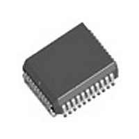
TXC02050AIPL Transwitch Corporation, TXC02050AIPL Datasheet - Page 6

TXC02050AIPL
Manufacturer Part Number
TXC02050AIPL
Description
Manufacturer
Transwitch Corporation
Datasheet
1.TXC02050AIPL.pdf
(26 pages)
Specifications of TXC02050AIPL
Operating Temperature (min)
-40C
Operating Temperature Classification
Industrial
Operating Temperature (max)
85C
Package Type
PLCC
Rad Hardened
No
Lead Free Status / Rohs Status
Not Compliant
MRT Control Leads
Note 1: Setting
ports.
Symbol
BERCK
PNENB
LBKRX
LBKTX
RXAIS
RXDIS
LOW
DCK
LBKTX
Pin No.
21
24
25
26
3
4
8
9
and
LBKRX
I/O/P
I
I
I
I
I
I
I
I
low simultaneously will cause invalid outputs at the receive terminal and transmit line
CMOSr
CMOSr
CMOSr
CMOSr
CMOSr
CMOSr
Type
TTLr
TTL
- 6 -
Receive Alarm Indication Signal: When RXAIS is
low, the MRT generates AIS (all ones signal) for the
terminal side receive output data. The line side
receive data path is disabled. The reference clock
(DCK) provides the clock source required for generat-
ing AIS.
Bit Error Rate Clock: This clock establishes the time
base for estimating the coding violation error rate. For
34 Mbit/s operation the clock frequency must be 6
kHz, and for 8 Mbit/s operation the clock frequency
must be 1.5 kHz. This pin should be left open for P
and N mode operation.
P And N Enable: When PNENB is low, the P and N
rail interface is enabled, and the HDB3 codec is
bypassed. When PNENB is high, the terminal side I/O
data is NRZ and the HDB3 codec is enabled. This pin
must be held low for 6 Mbit/s operation.
Reference Clock: Operating frequency reference
clock. For receive signal clock recovery,
frequency accuracy is adequate. If the transmit and
receive AIS features are used, the frequency accuracy
must be 20 ppm for 34368 kbit/s and 30 ppm for
8448 and 6312 kbit/s operation. The duty cycle
requirement for this clock signal is 50% 5% as mea-
sured at the 1.4V TTL threshold level.
Receive Disable: When RXDIS is low, the receive
side of the MRT is disabled and the RN, RP/RD,
CLKO and CLKO output leads are forced to a high
impedance state.
Loopback Receive: When LBKRX is low, the MRT
loops back receive data as transmit data. The receive
data is also sent to the terminal side, but the transmit
data input on the terminal side is disabled. (Note 1)
Loopback Transmit: When LBKTX is low, the MRT
loops back transmit data as receive data. The transmit
data is sent on the line side, but the receive data input
on the line side is disabled. (Note 1)
Low Frequency: When LOW is low, the MRT enables
equalization and input attenuator settings for 6312 or
8448 kbit/s operation. This lead also controls the clock
recovery high/low frequency range circuit.
Name/Function
200 ppm
Ed. 3, April 1994
TXC-02050-MB
MRT


