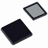
AD9911BCPZ Analog Devices Inc, AD9911BCPZ Datasheet - Page 27

AD9911BCPZ
Manufacturer Part Number
AD9911BCPZ
Description
IC DDS 500MSPS DAC 10BIT 56LFCSP
Manufacturer
Analog Devices Inc
Datasheet
1.AD9911BCPZ-REEL7.pdf
(44 pages)
Specifications of AD9911BCPZ
Resolution (bits)
10 b
Master Fclk
500MHz
Tuning Word Width (bits)
32 b
Voltage - Supply
1.71 V ~ 1.96 V
Operating Temperature
-40°C ~ 85°C
Mounting Type
Surface Mount
Package / Case
56-LFCSP
Transmitting Current
73mA
Data Rate
800Mbps
Rf Ic Case Style
LFCSP
No. Of Pins
56
Supply Voltage Range
1.71V To 1.89V, 3.135V To 3.465V
Operating Temperature Range
-40°C To +85°C
Msl
MSL 3 - 168 Hours
Lead Free Status / RoHS Status
Lead free / RoHS Compliant
For Use With
AD9911/PCBZ - BOARD EVAL FOR AD9911AD9911/PCB - BOARD EVAL FOR AD9911
Lead Free Status / Rohs Status
Compliant
Available stocks
Company
Part Number
Manufacturer
Quantity
Price
Company:
Part Number:
AD9911BCPZ
Manufacturer:
NXP
Quantity:
173
Part Number:
AD9911BCPZ
Manufacturer:
ADI/亚德诺
Quantity:
20 000
Ramp Rate Timer
The ramp rate timer is a loadable 8-bit down counter. It
generates the clock signal to the 10-bit counter, which in turn
generates the internal scale factor. The formula for calculating
the amplitude ramp rate time is
Where x is the decimal value in Register 00x06 Bits <23:16>.
At 500 MSPS operation (SYNC_CLK =125 MHz), the
minimum time interval between steps is 1/125 MHz × 1 = 8 ns.
The maximum time interval is (1/125 MHz) × 255 = 2.04 μs.
Δ
t =
PROFILE REGISTERS
ASK MODULATION
( )
ACCUMULATOR
LINEAR SWEEP
x
MODULATION
TEST TONE
/
SYNC
FOR
DDS CORE
_
COS(X)
CLK
(
Hz
10
10
10
)
AMPLITUDE SCALE
RAMP UP/DOWN
(ACR) <0:9>
REGISTER
FACTOR
MANUAL
(RU/RD)
10
MUX
MULTIPLIER ENABLE
AMPLITUDE
ACR <12>
Figure 46. Output Amplitude Control Configurations
0
1
10
10
0 1
Rev. 0 | Page 27 of 44
DAC
INCREMENT/
DECREMENT
STEP SIZE
ACR <15:14>
10
10
0
PROFILE/SDIO_1:3
0
1
The ramp rate timer is loaded with the value of the ASF every
time the counter reaches 1 (decimal). This load and count down
operation continues for as long as the timer is enabled unless
the timer is forced to load before reaching a count of 1.
If the load ARR timer bit ACR <10> is set, the ramp rate timer
is loaded if any of the following three incidents transpire: an I/O
update occurs, a profile pin changes, or the timer reaches a
See through Table 13 through Table 18 for RU/RD pin
assignments.
2
PINS
10-BIT BINARY
OUT
UP/DOWN
COUNTER
INC/DEC EN
SYNC_CLK
UP/DN
HOLD
RAMP UP/DOWN
ACR <11>
ENABLE
(RU/RD)
LOAD ARR
TIMER
BIT ACR <10>
8-BIT BINARY
LOAD
(ACR BITS <23:16>)
COUNTER
DOWN
RAMP RATE
AMPLITUDE
REGISTER
DATA
8
EN
AUTO RAMP
UP/DOWN
(RU/RD)
SYNC
CLOCK
AD9911


