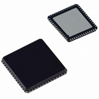
AD9911BCPZ Analog Devices Inc, AD9911BCPZ Datasheet - Page 26

AD9911BCPZ
Manufacturer Part Number
AD9911BCPZ
Description
IC DDS 500MSPS DAC 10BIT 56LFCSP
Manufacturer
Analog Devices Inc
Datasheet
1.AD9911BCPZ-REEL7.pdf
(44 pages)
Specifications of AD9911BCPZ
Resolution (bits)
10 b
Master Fclk
500MHz
Tuning Word Width (bits)
32 b
Voltage - Supply
1.71 V ~ 1.96 V
Operating Temperature
-40°C ~ 85°C
Mounting Type
Surface Mount
Package / Case
56-LFCSP
Transmitting Current
73mA
Data Rate
800Mbps
Rf Ic Case Style
LFCSP
No. Of Pins
56
Supply Voltage Range
1.71V To 1.89V, 3.135V To 3.465V
Operating Temperature Range
-40°C To +85°C
Msl
MSL 3 - 168 Hours
Lead Free Status / RoHS Status
Lead free / RoHS Compliant
For Use With
AD9911/PCBZ - BOARD EVAL FOR AD9911AD9911/PCB - BOARD EVAL FOR AD9911
Lead Free Status / Rohs Status
Compliant
Available stocks
Company
Part Number
Manufacturer
Quantity
Price
Company:
Part Number:
AD9911BCPZ
Manufacturer:
NXP
Quantity:
173
Part Number:
AD9911BCPZ
Manufacturer:
ADI/亚德诺
Quantity:
20 000
AD9911
SWEEP AND PHASE ACCUMULATOR CLEARING
FUNCTIONS
The AD9911 provides two different clearing functions. The first
function is a continuous zeroing of the sweep logic and phase
accumulator (clear and hold). CFR <3> clears the sweep
accumulator and CFR <1> clears the phase accumulator
The second function is a clear and release or automatic zeroing
function. CFR <4> is the automatic clear sweep accumulator bit
and CFR <2> is the automatic clear phase accumulator bit.
Continuous Clear Bits
The continuous clear bits are static control signals that, when
high, hold the respective accumulator at 0. When the bit is
programmed low, the respective accumulator is released.
Clear and Release Bits
The auto clear sweep accumulator bit, when set, clears and
releases the sweep accumulator upon an I/O update or a change
in the profile input pins. The auto clear phase accumulator,
when set, clears and releases the phase accumulator upon an
I/O update or a change in the profile pins. The automatic clear-
ing function is repeated for every subsequent I/O update or
change in profile pins until the clear and release bits are cleared
via the I/O port.
OUTPUT AMPLITUDE CONTROL
The output amplitude may be controlled via one of four
methods. Output amplitude control is implemented by the use
of the 10-bit output scale factor (multiplier). See Figure 46 for
output amplitude control configurations. For further details on
the corresponding methods, see the Shift Keying Modulation
section and the Linear Sweep (Shaped) Modulation Mode
sections. The remaining methods (Manual and Automatic
RU/RD) are described in this section.
FTW1
FTW0
f
OUT
SINGLE–TONE
MODE
PS<1> = 0
A
Figure 45. Linear Sweep Enabled-No Dwell Bit Cleared
LINEAR SWEEP MODE
PS<1> = 1
Rev. 0 | Page 26 of 44
The RU/RD feature is used to control an on/off emission from
the DAC. This helps reduce the adverse spectral impact of
abrupt burst transmissions of digital data. The multiplier can be
bypassed by clearing the multiplier enable bit (ACR <12> = 0).
Automatic and manual RU/RD modes are supported. The
automatic mode generates a zero to full-scale (10-bits) linear
ramp at a rate set using the amplitude ramp rate control register
(ACR <23:16>). Ramp initiation and direction (up/down) is
controlled using either the profile pins or the SDIO1:3 pins.
See Table 21. Manual mode is selected by programming ACR
<12:11> = 10. In this mode, the user sets the output amplitude
by writing to the amplitude scale factor value in the amplitude
control register (Register 0x06 Bits <9:0>).
Automatic RU/RD Mode Operation
The automatic RU/RD mode is entered by setting ACR <12:11>
= 11. In this mode, the scale factor is internally generated and
applied to the multiplier input port for scaling the output. The
scale factor is the output of a 10-bit counter that increments/
decrements at a rate set by the 8-bit output ramp rate in Register
0x06 Bits <23:16>. The scale factor increments if the external
pin is high and decrements if the pin is low. The scale factor
step size is selected using the ACR<15:14>. Table 20 details the
step size options available.
Table 20.
Autoscale Factor Step Size
ASF <15:14> (Binary)
00
01
10
11
The amplitude scale factor register allows the device to ramp to
a value less than full scale.
B
PS<1> = 0
Increment/Decrement Size
1
2
4
8
TIME


