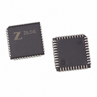
Z8927320VSG Zilog, Z8927320VSG Datasheet - Page 45

Z8927320VSG
Manufacturer Part Number
Z8927320VSG
Description
DSP 20MHZ 16-BIT W/ A/D 44-PLCC
Manufacturer
Zilog
Series
Z892x3r
Type
Fixed Pointr
Datasheet
1.Z8937320FSC00TR.pdf
(60 pages)
Specifications of Z8927320VSG
Interface
SPI, 3-Wire Serial
Clock Rate
20MHz
Non-volatile Memory
OTP (16 kB)
On-chip Ram
1kB
Voltage - I/o
5.00V
Voltage - Core
5.00V
Operating Temperature
0°C ~ 70°C
Mounting Type
Surface Mount
Package / Case
44-LCC (J-Lead)
Lead Free Status / RoHS Status
Lead free / RoHS Compliant
Available stocks
Company
Part Number
Manufacturer
Quantity
Price
Company:
Part Number:
Z8927320VSG
Manufacturer:
Zilog
Quantity:
50
ZiLOG
SERIAL PERIPHERAL INTERFACE
The Z893x3 incorporates a Serial Peripheral Interface (SPI)
for communication with other microcontrollers and periph-
erals. The SPI can be operated either as the system Master,
or as a system Slave. The SPI consists of three registers: the
SPI Control Register (Bank15/EXT4), the SPI Re-
ceive/Buffer Register (RxBUF), and the SPI Shift Register.
SPI Data Access
Receive operations are double buffered. Bank0/EXT3 ac-
cesses both RxBUF for read (receive) operations, and the
SPI shift register for write (transmit) operations.
Master Mode Operation
The DSP must first activate the target slave’s select pin
through an I/O port. Loading data into the SPI Shift Register
initiates the transfer. Data is transferred out the SDO pin to
the slave one data bit per SCLK cycle. The MSB is shifted
out first. At the conclusion of the transfer, the Receive Byte
DS000202-DSP0599
Bank 0/EXT 3 Register
Bits 7Ð0 SPI Data (SPI Shift Register for transmit and RxBUF for receive)
Bit 14
Bit 15
D15 D14
Receive Character Available
Receive Character Overrun
Mode of Operation
SPI Clock Source Select (Master)
SCLK Polarity
Received Byte Available
0 = Slave
1 = Master
0 = System Clock divided down.
1 = C/T0
0 = Transmit on Falling Edge, Receive on Rising Edge
1 = Transmit on Rising Edge, Receive on Falling Edge
Figure 39. SPI Data Access
D7 D6 D5 D4 D3 D2 D1 D0
Figure 40. SPI Control Register
Bank15/EXT4 (LSB)
D7 D6 D5 D4 D3 D2 D1 D0
SPI Control Register
This register is the Low byte of Bank15/EXT4. It is a
read/write register that controls Master/Slave selection, SS
polarity, clock source and phase selection, and indicates
byte available and data overrun conditions. The control reg-
ister is multifunction depending on Master/Slave mode se-
lection.
In Master mode, Bit 6 defines the SPI clock source. A “1”
selects SCLK = C/T0 output, and a “0” selects SCLK = Sys-
tem Clock divided down by 2, 4, 8, or 16, as determined by
bits 1 and 2.
In Slave Mode, bit 1 is the Receive Byte Overrun flag. This
flag can be cleared by writing a “0” to this bit. Bit 2 is the
SDO output enable.A “0” tristates SDO, a “1” enables data
output on SDO. Bit 4 signals that a receive byte is available
in the RxBUF Register. If the associated interrupt enable
bit is enabled, an interrupt is generated.
Available flag is set, and if enabled, an SPI interrupt is gen-
erated. The Receive Byte Available flag is reset when Rx-
BUF is read.
16-Bit Digital Signal Processors with A/D Converter
SPI Enable
Receive Byte Overrun (Slave)
Output Enable(Slave)
SCLK Frequency (Master)
Slave Select Polarity
0 = Disable (default)
1 = Enable
0 = Tri-State SDO
1 = Enable SDO as Output
00 = System Clock 2
01 = System Clock 4
10 = System Clock 8
11 = System Clock 16
0 = SS Active Low (default)
1 = SS Active High
Z89223/273/323/373
45


