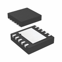
AD7156BCPZ-REEL7 Analog Devices Inc, AD7156BCPZ-REEL7 Datasheet - Page 24

AD7156BCPZ-REEL7
Manufacturer Part Number
AD7156BCPZ-REEL7
Description
IC CDC 2CH 12BIT 1.8V 10LFCSP
Manufacturer
Analog Devices Inc
Type
Capacitance-to-Digital Converterr
Datasheet
1.AD7156BCPZ-REEL7.pdf
(28 pages)
Specifications of AD7156BCPZ-REEL7
Resolution (bits)
12 b
Data Interface
Serial
Sampling Rate (per Second)
100k
Voltage Supply Source
Single Supply
Voltage - Supply
1.8 V ~ 3.6 V
Operating Temperature
-40°C ~ 85°C
Mounting Type
Surface Mount
Package / Case
10-LFCSP
Sampling Rate
100SPS
Input Channel Type
Single Ended
Supply Voltage Range - Analog
1.8V To 3.6V
Supply Current
70µA
Lead Free Status / RoHS Status
Lead free / RoHS Compliant
Lead Free Status / RoHS Status
Lead free / RoHS Compliant, Lead free / RoHS Compliant
Other names
AD7156BCPZ-REEL7TR
AD7156
HARDWARE DESIGN CONSIDERATIONS
OVERVIEW
The AD7156 is an interface to capacitive sensors.
On the input side, Sensor C
the AD7156 EXC and CIN pins. The way it is connected and the
electrical parameters of the sensor connection, such as parasitic
resistance or capacitance, can affect the system performance.
Therefore, any circuit with additional components in the capacitive
front end, such as overvoltage protection, has to be carefully
designed, considering the AD7156 specified limits and informa-
tion provided in this section.
On the output side, the AD7156 can work as a standalone device,
using the power-up default register settings and flagging the
result on the digital outputs. Alternatively, the AD7156 can be
interfaced to a microcontroller via the 2-wire serial interface,
offering flexibility by overwriting the AD7156 register values
from the host with a user-specific setup.
PARASITIC CAPACITANCE TO GROUND
The CDC architecture used in the AD7156 measures the
capacitance, C
CIN pins. In theory, any capacitance, C
not affect the CDC result (see Figure 42).
The practical implementation of the circuitry in the chip implies
certain limits, and the result is gradually affected by capacitance
to ground (for information about the allowed capacitance to
GND for CIN and information about excitation see Table 1
and Figure 4 to Figure 9).
C
C
GND1
GND2
Figure 42. Parasitic Capacitance to Ground
X
, connected between the EXC pins and the
C
X
EXC
CIN
X
can be connected directly between
GND
CDC
, to ground should
DATA
Rev. 0 | Page 24 of 28
PARASITIC RESISTANCE TO GROUND
The AD7156 CDC result is affected by a leakage current from
C
The equivalent resistance between C
maximized (see Figure 43). For more information, see Figure 10
to Figure 13.
PARASITIC PARALLEL RESISTANCE
The AD7156 CDC measures the charge transfer between the
EXC and CIN pins. Any resistance connected in parallel to the
measured capacitance, C
resistance of the sensor, also transfers charge. Therefore, the
parallel resistor is seen as an additional capacitance in the
output data. The equivalent parallel capacitance (or error
caused by the parallel resistance) can be approximately
calculated as
where:
R
f
For additional information, see Figure 15.
EXC
P
X
is the parallel resistance.
to ground; therefore, C
is the excitation frequency.
R
R
C
GND1
GND2
P
C
X
=
R
P
R
×
P
f
EXC
Figure 43. Parasitic Resistance to Ground
1
CIN
C
EXC
Figure 44. Parasitic Parallel Resistance
X
EXC
CIN
×
4
X
X
(see Figure 44), such as the parasitic
should be isolated from the ground.
X
CDC
and ground should be
CDC
DATA
DATA


