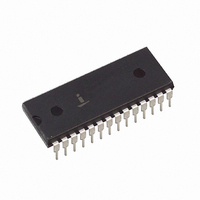
HI3-7159A-5 Intersil, HI3-7159A-5 Datasheet - Page 11

HI3-7159A-5
Manufacturer Part Number
HI3-7159A-5
Description
CONV A/D 5.5 DIGITIC MPU 28-DIP
Manufacturer
Intersil
Datasheet
1.HI3-7159A-5.pdf
(14 pages)
Specifications of HI3-7159A-5
Number Of Bits
8
Sampling Rate (per Second)
200k
Data Interface
Serial, Parallel
Number Of Converters
1
Voltage Supply Source
Analog and Digital, Dual ±
Operating Temperature
0°C ~ 70°C
Mounting Type
Through Hole
Package / Case
28-DIP (0.600", 15.24mm)
Lead Free Status / RoHS Status
Contains lead / RoHS non-compliant
Available stocks
Company
Part Number
Manufacturer
Quantity
Price
f
------------------------------------------- -
It may also be possible to directly program the host’s serial
hardware for operation at nonstandard baud rates, allowing
HI-7159A operation at any arbitrary frequency. For example:
50Hz AC rejection requires a 2MHz clock. At this frequency
the “9600” baud rate becomes 7812.5 baud. The host’s
UART must be programmed with the proper divider to
operate at this baud rate. The data clock (see Figure 2) is
defined as 16 times the baud rate, so the data clock of this
configuration would be 125kHz. The data clock can also be
determined by dividing the oscillator (clock) frequency by the
correct divider from Table 12.
The following equation determines the divider needed to
operate the HI-7159A at any given crystal frequency:
Once determined, the new divider must be written directly to
the Host’s UART. Most PC compatibles use an 8250 UART with
a 1.8432MHz crystal, so the proper divider for the 2MHz
example given above would be 15. Again, these considerations
apply only to Serial Modes 1 and 2. Parallel and Serial Mode 0
communication rates are independent of crystal frequency.
Conversion Time
The conversion time of the HI-7159A is a function of the
crystal frequency and the type of conversion being made.
The conversion times for f
Table 13. At other clock frequencies the times may be
calculated from the following formula:
t
where the constant C is determined from Table 13.
Component Selection
Three external passive components must be chosen for the
HI-7159A: the integrating capacitor (C
resistor (R
chosen based on the crystal frequency, the reference voltage
(V
the analog components necessary for the HI-7159A to function.
Divider 7159A
CLOCK
CONV
f = 2.4MHz
C
REF
BAUD RATE SELECTED
), and the desired integrating current. Figure 8 illustrates
=
7159A
-------------------- -
f
CLOCK
INT
“19200”
TABLE 12. CRYSTAL DIVIDER RATIOS
“1200”
“9600”
C
“300”
), and the reference capacitor (C
TABLE 13. CONVERSION TIMES
=
320,000
COMP
133ms
f
--------------------------------------------------------------- -
CRYSTAL
5
Divider Host UART
1
/
2
CLOCK
UNCOMP
CONVERSION TYPE
66.7ms
160,000
Host UART
11
5
1
/
2
= 2.4MHz are shown in
CRYSTAL DIVIDER
INT
), the integrating
33.3ms
80,000
COMP
=
4
1
Data Clock
/
512
128
2
REF
16
8
). They are
UNCOMP
16.7ms
40,000
4
1
/
2
HI-7159A
NOTE: C
performance may be degraded.
The reference capacitor and integrating components can
either be selected from Table 14, or calculated from the
following equations.
C
conversion. Its value is determined by two considerations: it
must be small enough to be fully charged from its
discharged state at power-on; yet it also must be large
enough to supply current to the circuit during conversion
without significantly drooping from its initial value. For
2.4MHz operation, a 1 F capacitor is recommended. The
equation for other frequencies is:
The values of R
maximum integration current and the maximum integrator
output voltage swing. The maximum integration current and
voltage swing occurs when V
recommended integration current for the HI-7159A is
5mA - 10mA. This will help determine the value of R
since:
where V
C
V
I
2.4MHz
1.2MHz
600kHz
REF LO
INT
V
REF HI
TABLE 14. RECOMMENDED COMPONENT VALUES vs
REF
REF
V
A
IN LO
IN HI
GND
f
CLOCK
=
acts as a voltage source at different times during a
FIGURE 8. ANALOG COMPONENTS AND INPUTS
=
-------------
R
V
IN
INT
-------------------- -
f
INT
+5V
CLOCK
IN
9
10
12
13
11
1
2.5
= V
V
MUST be a high quality polypropylene capacitor or
CLOCK FREQUENCY
CC
HI-7159A
so R
IN HI
INT
26
D
GND
400k
360k
330k
and C
- V
INT
R
INT
IN LO
27
14
=
2
3
4
5
6
7
8
X
TAL
INT
---------- - ,
I
V
INT
C
C
C
C
INT OUT
INT IN
BUF OUT
V
IN
REF
REF
REF+
REF+
EE
= 2 x V
IN
are selected by choosing the
-5V
A
-
= full scale = 2 X V
- GUARD
GND
GUARD
0.022 F
0.047 F
0.01 F
C
C
REF
R
INT
INT
INT
C
.
REF
D
GND
REFERENCE
CAPACITOR
C
1.0 F
2.2 F
4.7 F
GUARD
REF
RINGS
REF
INT
. The
,


