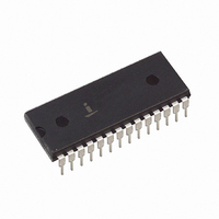
HI3-7159A-5 Intersil, HI3-7159A-5 Datasheet

HI3-7159A-5
Specifications of HI3-7159A-5
Available stocks
Related parts for HI3-7159A-5
HI3-7159A-5 Summary of contents
Page 1
... In the serial modes, any one of four common baud rates is available. Ordering Information TEMP. o PART NUMBER RANGE ( C) PACKAGE HI3-7159A PDIP Pinout HI-7159A (PDIP) TOP VIEW SEL ...
Page 2
Absolute Maximum Ratings Supply Voltage V to GND ( -0.3V < GND GND V to GND ( ...
Page 3
DC Electrical Specifications Test Conditions CLOCK Compensated Mode, Unless Otherwise Specified PARAMETER Input Low Voltage Input High Voltage Output Low Voltage Output High Voltage Three-State Leakage Current, Pins 18-25, I ...
Page 4
Timing Waveforms DATA IN FIGURE 1A. WRITE DATA OUT FIGURE 1D. READ CLK (PIN 15) RXD/TXD (PIN 16) D0 ...
Page 5
Pin Descriptions PIN SYMBOL INT OUT 3 INT IN 4 BUF OUT Guard REF REF REF Guard REF 9 V REF ...
Page 6
Theory of Operation 1 The HI-7159A attains its 5 / digit resolution through the use 2 of multiple integrations per conversion, creating an effective integrator swing greater than the supply rails, and a successive integration technique used to measure the ...
Page 7
Serial Mode 1 Serial Mode 1 is selected by tying SMS0 (Pin 18) low, SMS1 (Pin 19) high, and SEL (Pin 28) low (Figure 4B). In this mode the HI-7159A interface emulates a UART, reading and writing data in serial ...
Page 8
Serial Mode 2 Serial Mode 2 is selected by tying SEL (pin 28) low, SMS0 (pin 18) high, and SMS1 (pin 19) low, as shown in Figure 4C. This mode of operation is identical to Serial Mode 1, except that ...
Page 9
TABLE 7. REQUEST BYTE FORMAT, SERIAL MODE 2 (SENT TO HI-7159A) (RESERVED TABLE 8. STATUS BYTE FORMAT (RECEIVED FROM HI-7159A) CONVERTER † † UPDATE STATUS ( ) ...
Page 10
SEND COMMAND BYTE (INITIATE SINGLE CONVERSION) GET STATUS BYTE YES GET DIGIT BYTES CONVERSION RESULT IS VALID FIGURE 5. READING THE HI-7159A IN THE SINGLE CONVERSION MODE GET STATUS BYTE YES GET ...
Page 11
It may also be possible to directly program the host’s serial hardware for operation at nonstandard baud rates, allowing HI-7159A operation at any arbitrary frequency. For example: 50Hz AC rejection requires a 2MHz clock. At this frequency the “9600” baud ...
Page 12
Therefore values of R should be between 200k and INT 400k . The exact value of R may be altered to get the INT exact integrator swing desired after choosing a standard capacitor value for C . INT The most ...
Page 13
Die Characteristics DIE DIMENSIONS: 5817 m x 3988 m METALLIZATION: Type: SiAl Å Å Thickness: 10k 1k BUF INT INT OUT IN OUT - C REF GUARD - C REF C + REF C + REF GUARD V REF HI ...
Page 14
... Accordingly, the reader is cautioned to verify that data sheets are current before placing orders. Information furnished by Intersil is believed to be accurate and reliable. However, no responsibility is assumed by Intersil or its subsidiaries for its use; nor for any infringements of patents or other rights of third parties which may result from its use ...


