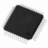
TSA1204IFT STMicroelectronics, TSA1204IFT Datasheet - Page 18

TSA1204IFT
Manufacturer Part Number
TSA1204IFT
Description
IC CONV A/D 2-CH 12-BIT 48-TQFP
Manufacturer
STMicroelectronics
Datasheet
1.TSA1204IFT.pdf
(31 pages)
Specifications of TSA1204IFT
Number Of Bits
12
Sampling Rate (per Second)
20M
Data Interface
Parallel
Number Of Converters
2
Power Dissipation (max)
155mW
Voltage Supply Source
Analog and Digital
Operating Temperature
-40°C ~ 85°C
Mounting Type
Surface Mount
Package / Case
48-TQFP
Lead Free Status / RoHS Status
Lead free / RoHS Compliant
Other names
497-5435-2
TSA1204IFT
TSA1204IFT
Available stocks
Company
Part Number
Manufacturer
Quantity
Price
Company:
Part Number:
TSA1204IFT
Manufacturer:
PHI
Quantity:
45
Company:
Part Number:
TSA1204IFT
Manufacturer:
STMicroelectronics
Quantity:
10 000
Application information
8.4
8.5
18/31
Figure 27. DC-coupled 2 V
Figure 27
analog input while VREFM is connected to ground; the differential amplitude obtained is
2 V
Clock input
The quality of your TSA1204 converter is very dependent on your clock input accuracy, in
terms of aperture jitter; the use of a low jitter crystal controlled oscillator is recommended.
Further points to consider in your implementation are:
●
●
●
Power consumption optimization
The internal architecture of the TSA1204 makes it possible to optimize power consumption
according to the sampling frequency of the application. For this purpose, an external resistor
is placed between I
optimized over the full sampling range (0.5 Msps up to 20 Msps).
The TSA1204 combines the highest performance and the lowest consumption at 20 Msps
when R
environment.
In the lower sampling frequency range, this value of resistor may be adjusted in order to
decrease the analog current without any degradation of the dynamic performance.
Table 12
pp
The duty cycle must be between 45% and 55%.
The clock power supplies must be independent from the ADC output supplies to avoid
digital noise modulation on the output.
When powered-on, the circuit needs several clock periods to reach its normal operating
conditions. Therefore, it is recommended to keep the circuit clocked to avoid random
states before applying the supply voltages.
.
pol
gives some values to illustrate this.
shows a DC-coupled configuration with forced VREFP and INCM to the 1 V DC
is equal to 54 kΩ. This value is nevertheless dependent on the application and the
POL
VREFP-VREFM = 1 V
analog
analog
and the analog ground pins. Therefore, the total dissipation can be
pp
DC
DC
differential analog input
AC+DC
330pF
VINB
VIN
10nF
TSA1204
INCM
VREFM
VREFP
4.7μF
TSA1204


