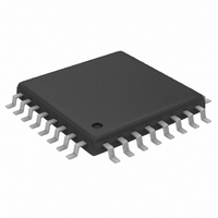
MAX1498ECJ+ Maxim Integrated Products, MAX1498ECJ+ Datasheet - Page 19

MAX1498ECJ+
Manufacturer Part Number
MAX1498ECJ+
Description
IC ADC 4 1/2DIG W/LED DVR 32TQFP
Manufacturer
Maxim Integrated Products
Datasheet
1.MAX1496EAI.pdf
(24 pages)
Specifications of MAX1498ECJ+
Number Of Bits
4.5 Digit
Sampling Rate (per Second)
5
Number Of Converters
1
Power Dissipation (max)
1.65W
Voltage Supply Source
Analog and Digital
Operating Temperature
-40°C ~ 85°C
Mounting Type
Surface Mount
Package / Case
32-LQFP
Lead Free Status / RoHS Status
Lead free / RoHS Compliant
(PD x T
VLED - V
ensure it operates safely:
For a 28-pin PDIP package, VLED - V
the following condition to ensure it operates safely:
The MAX1447/MAX1498 TQFP package can operate
safely for all supply voltages provided V
Integral nonlinearity (INL) is the deviation of the values
on an actual transfer function from a straight line. This
straight line is either a best-straight-line fit or a line
drawn between the end points of the transfer function,
once offset and gain errors have been nullified. INL for
the MAX1447/MAX1496/MAX1498 is measured using
the end-point method.
Differential nonlinearity (DNL) is the difference between
an actual step width and the ideal value of ±1 LSB. A
DNL error specification of less than ±1 LSB guarantees
no missing codes and a monotonic transfer function.
(VLED - V
VLED - V
PD x T
PD (max) = +40°C /+105.3°C/W = 380mW
JA
PD (max) = +40°C / +70°C/W = 571mW
) max = (+125°C) - (+85°C) = +40°C
DIODE
DIODE
DIODE
JA
0.8V < VLED - V
0.8V < VLED - V
(max) = (+125°C) - (+85°C) = +40°C
VLED - V
VLED - V
should have the following condition to
) = [380mW - (5.25V x 2mA) - 5.25V x
= [571mW - (5.25V x 2mA) - 5.25V x
1.080mA] / [(127 / 128) x 25.5mA x 8]
1.080mA] / [(127 / 128) x 25.5mA x 8]
______________________________________________________________________________________
28-Pin PDIP-Package Example
DIODE
DIODE
DIODE
DIODE
3.5- and 4.5-Digit, Single-Chip ADCs
= 1.854V
= 2.80V
32-Pin TQFP Package
< 1.854V
< 2.80V
DIODE
Definitions
DIODE
should have
> 1.5V.
DNL
INL
Rollover error is defined as the absolute-value differ-
ence between a near positive full-scale reading and
near negative full-scale reading. Rollover error is tested
by applying a full-scale positive voltage, swapping
AIN+ and AIN-, and adding the results.
Ideally, with AIN+ connected to AIN-, the MAX1447/
MAX1496/MAX1498 LED displays zero. Zero input
reading is the measured deviation from the ideal zero
and the actual measured point.
Gain error is the amount of deviation between the mea-
sured full-scale transition point and the ideal full-scale
transition point.
Common-mode rejection (CMR) is the ability of a
device to reject a signal that is common to both input
terminals. The common-mode signal can be either an
AC or a DC signal or a combination of the two. CMR is
often expressed in decibels.
Normal-mode rejection is a measure of how much output
changes when 50Hz and 60Hz signals are injected into
only one of the differential inputs. The MAX1447/
MAX1496/MAX1498 sigma-delta converter uses its inter-
nal digital filter to provide normal-mode rejection to both
50Hz and 60Hz power-line frequencies simultaneously.
Power-supply rejection ratio (PSRR) is the ratio of the input
supply change (in volts) to the change in the converter
output (in volts). It is typically measured in decibels.
Normal-Mode 50Hz and 60Hz Rejection
with LED Drivers
Power-Supply Rejection Ratio
Common-Mode Rejection
Zero Input Reading
(Simultaneously)
Rollover Error
Gain Error
19


