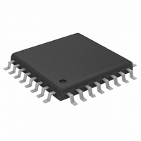
MAX1498ECJ+ Maxim Integrated Products, MAX1498ECJ+ Datasheet - Page 16

MAX1498ECJ+
Manufacturer Part Number
MAX1498ECJ+
Description
IC ADC 4 1/2DIG W/LED DVR 32TQFP
Manufacturer
Maxim Integrated Products
Datasheet
1.MAX1496EAI.pdf
(24 pages)
Specifications of MAX1498ECJ+
Number Of Bits
4.5 Digit
Sampling Rate (per Second)
5
Number Of Converters
1
Power Dissipation (max)
1.65W
Voltage Supply Source
Analog and Digital
Operating Temperature
-40°C ~ 85°C
Mounting Type
Surface Mount
Package / Case
32-LQFP
Lead Free Status / RoHS Status
Lead free / RoHS Compliant
The MAX1447/MAX1496/MAX1498 feature data-hold
circuitry. When activated (HOLD is set to AV
MAX1447/MAX1498 or to V
device holds the current reading on the LED.
Connect the differential inputs of the MAX1447/
MAX1496/MAX1498 to the bridge network of the strain
gauge. In Figure 8, the analog supply voltage powers
the bridge network and the MAX1447/MAX1496/
MAX1498, along with the reference voltage. The
MAX1447/MAX1496/MAX1498 handle an analog input
voltage range of ±200mV and ±2V full scale. The ana-
log/reference inputs of the parts allow the analog input
range to have an absolute value of anywhere between
-2.2V and +2.2V.
Figure 9 shows a connection from a thermocouple to
the MAX1447/MAX1496/MAX1498. In this application,
the MAX1447/MAX1496/MAX1498 take advantage of
the on-chip input buffers that allow large source imped-
ances on the front end. The decoupling capacitors
reduce noise pickup from the thermocouple leads. To
place the differential voltage from the thermocouple at
a suitable common-mode voltage, the AIN- input of the
MAX1447/MAX1496/MAX1498 is biased to GND. Use
an external temperature sensor, such as the DS75, and
a microcontroller to perform cold-junction temperature
compensation.
3.5- and 4.5-Digit, Single-Chip ADCs
with LED Drivers
Figure 10. MAX1447/MAX1498 Transfer Function, ±2V Range
16
______________________________________________________________________________________
- 1 - - - -
-19,999
1 - - - -
19,999
- 0
- 1
- 2
LED
2
1
0
-2V
Thermocouple Measurement
Strain-Gauge Measurement
ANALOG INPUT VOLTAGE
-100µV 100µV
DD
0
for the MAX1496), the
+2V
DD
for the
Hold
Figures 10–13 show the transfer functions of the
MAX1447/MAX1496/MAX1498.
The transfer function for the MAX1447/MAX1498 with
AIN+ - AIN- ≥ 0, RANGE = GND is:
The transfer function for the MAX1447/MAX1498 with
AIN+ - AIN- < 0, RANGE = GND is:
The transfer function for the MAX1447/MAX1498 with
AIN+ - AIN- ≥ 0, RANGE = DV
The transfer function for the MAX1447/MAX1498 with
AIN+ - AIN- < 0, RANGE = DV
Figure 11. MAX1447/MAX1498 Transfer Function, ±200mV Range
COUNT
COUNT
COUNT
- 1 - - - -
COUNT
-19,999
1 - - - -
19,999
- 0
- 1
- 2
LED
2
1
0
=
=
=
1 024
.
1 024
-200mV
1 024
=
.
.
1 024
.
V
V
REF
AIN
V
V
V
REF
V
AIN
REF
AIN
+
+
ANALOG INPUT VOLTAGE
V
V
−
−
REF
+
+
-10µV
AIN
V
V
+
+
−
−
REF
AIN
−
−
V
V
DD
+
+
DD
V
V
REF
AIN
Transfer Functions
0
REF
−
−
−
AIN
−
10µV
V
V
is:
is:
−
REF
×
AIN
−
−
−
20 000
×
−
−
×
,
×
20 000
20 000
,
20 000
,
×
+200mV
,
×
+
10
10
+
1
1


