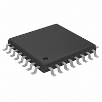
MAX1498ECJ+ Maxim Integrated Products, MAX1498ECJ+ Datasheet - Page 10

MAX1498ECJ+
Manufacturer Part Number
MAX1498ECJ+
Description
IC ADC 4 1/2DIG W/LED DVR 32TQFP
Manufacturer
Maxim Integrated Products
Datasheet
1.MAX1496EAI.pdf
(24 pages)
Specifications of MAX1498ECJ+
Number Of Bits
4.5 Digit
Sampling Rate (per Second)
5
Number Of Converters
1
Power Dissipation (max)
1.65W
Voltage Supply Source
Analog and Digital
Operating Temperature
-40°C ~ 85°C
Mounting Type
Surface Mount
Package / Case
32-LQFP
Lead Free Status / RoHS Status
Lead free / RoHS Compliant
The MAX1447/MAX1496/MAX1498 low-power, highly
integrated ADCs with LED drivers convert a ±2V differ-
ential input voltage (one count is equal to 100µV for the
MAX1447/MAX1498 and 1mV for the MAX1496) with a
sigma-delta ADC and output the result to an LED. An
additional ±200mV input range (one count is equal to
10µV for the MAX1447/MAX1498 and 100µV for the
MAX1496) is available to measure small signals with
increased resolution.
The devices operate from a single 2.7V to 5.25V power
supply and offer 3.5-digit (MAX1496) or 4.5-digit
(MAX1447/MAX1498) conversion results. An internal
2.048V reference, internal charge pump, and a high-accu-
racy on-chip oscillator eliminate external components.
The devices also feature on-chip buffers for the differen-
tial input signal and external-reference inputs, allowing
3.5- and 4.5-Digit, Single-Chip ADCs
with LED Drivers
10
MAX1496
19
20
21
22
23
24
25
26
27
28
______________________________________________________________________________________
—
—
—
—
—
PIN
MAX1447/
MAX1498
18
20
21
22
23
24
25
26
27
28
19
29
30
6
7
Detailed Description
LED_EN
SEGDP
NAME
SEGA
SEGB
SEGC
SEGD
SEGG
DPON
SEGE
SEGF
AV
DV
VLED
DIG3
DIG4
DD
DD
Digit 3 Driver
Segment A Driver
Segment B Driver
Segment C Driver
Segment D Driver
Segment E Driver
LED Display Segment Driver Supply. Connect to a +2.7V to +5.25V supply. Bypass with a
0.1µF capacitor to GLED.
Segment F Driver
Segment G Driver
Segment DP Driver
Analog Positive Supply Voltage. Connect AV
AV
Digital Positive Supply Voltage. Connect DV
DV
Digit 4 Driver
Active-High LED Enable. The MAX1447/MAX1498 display driver turns off when the LED_EN
is driven to logic low. The MAX1447/MAX1498 LED display driver turns on when LED_EN is
driven to logic high.
Decimal-Point Enable Input. Controls the decimal point of the LED. See the Decimal-Point
Control section. Connect to DV
decimal point.
DD
DD
to GND with a 0.1µF capacitor.
to GND with a 0.1µF capacitor.
direct interface with high-impedance signal sources. In
addition, they use continuous internal offset-calibration
and offer >100dB of 50Hz and 60Hz line-noise rejec-
tion. Other features include data hold and peak detec-
tion and overrange/underrange detection.
Internal protection diodes limit the analog input range
from VNEG to (AV
MAX1498, and from VNEG to (V
MAX1496. If the analog input exceeds this range, limit
the input current to 10mA.
The MAX1447/MAX1496/MAX1498 analog input/refer-
ence buffers allow the use of high-impedance signal
sources. The input buffers’ common-mode input range
allows the analog inputs and the reference to range from
-2.2V to +2.2V.
DD
(MAX1447/MAX1498) or V
Internal Analog Input/Reference Buffers
FUNCTION
Pin Description (continued)
DD
DD
to a +2.7V to +5.25V power supply. Bypass
to a +2.7V to +5.25V power supply. Bypass
DD
Analog Input Protection
+ 0.3V) for the MAX1447/
DD
(MAX1496) to enable the
DD
+ 0.3V) for the


