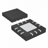
MAX1077ETC+ Maxim Integrated Products, MAX1077ETC+ Datasheet - Page 4

MAX1077ETC+
Manufacturer Part Number
MAX1077ETC+
Description
IC ADC 10BIT 1.5MSPS 12-TQFN
Manufacturer
Maxim Integrated Products
Datasheet
1.MAX1077ETC.pdf
(18 pages)
Specifications of MAX1077ETC+
Number Of Bits
10
Sampling Rate (per Second)
1.5M
Data Interface
MICROWIRE™, QSPI™, Serial, SPI™
Number Of Converters
1
Power Dissipation (max)
22mW
Voltage Supply Source
Analog and Digital
Operating Temperature
-40°C ~ 85°C
Mounting Type
Surface Mount
Package / Case
12-WQFN Exposed Pad
Number Of Adc Inputs
1
Architecture
SAR
Conversion Rate
1500 KSPs
Resolution
10 bit
Input Type
Differential
Interface Type
3-Wire (SPI, QSPI, MICROWIRE)
Voltage Reference
Internal 2.048 V or External
Supply Voltage (max)
3.6 V
Supply Voltage (min)
2.7 V
Maximum Power Dissipation
1349 mW
Maximum Operating Temperature
+ 85 C
Mounting Style
SMD/SMT
Minimum Operating Temperature
- 40 C
Lead Free Status / RoHS Status
Lead free / RoHS Compliant
1.5Msps, Single-Supply, Low-Power, True-
Differential, 10-Bit ADCs with Internal Reference
TIMING CHARACTERISTICS
(V
T
Figure 1. Detailed Serial-Interface Timing
4
Note 1: Relative accuracy is the deviation of the analog value at any code from its theoretical value after the gain error and the offset
Note 2: No missing codes over temperature.
Note 3: Conversion time is defined as the number of clock cycles (16) multiplied by the clock period.
Note 4: At sample rates below 10ksps, the input full-linear bandwidth is reduced to 5kHz.
Note 5: The listed value of three SCLK cycles is given for full-speed continuous conversions. Acquisition time begins on the 14th ris-
Note 6: Undersampling at the maximum signal bandwidth requires the minimum jitter spec for SINAD performance.
Note 7: 1.5Msps operation guaranteed for V
Note 8: Digital supply current is measured with the V
SCLK Pulse-Width High
SCLK Pulse-Width Low
SCLK Rise to DOUT Transition
DOUT Remains Valid After SCLK
CNVST Fall to SCLK Fall
CNVST Pulse Width
Power-Up Time; Full Power-Down
Restart Time; Partial Power-Down
A
CNVST
DD
DOUT
SCLK
= +25°C.)
_______________________________________________________________________________________
= +2.7V to +3.6V, V
error have been nulled.
ing edge of SCLK and terminates on the next falling edge of CNVST. The IC idles in acquisition mode between conversions.
speeds for V
t
PARAMETER
SETUP
L
< 2.7V.
L
t
CL
= V
t
DHOLD
t
t
CH
DOUT
DD
, f
SCLK
SYMBOL
t
t
PWR-UP
t
t
DHOLD
SETUP
DOUT
t
t
t
CSW
t
RCV
= 24MHz, 50% duty cycle, T
CH
CL
L
> 2.7V. See the Typical Operating Characteristics section for recommended sampling
V
V
(Note 7)
V
V
(Note 7)
C
C
V
V
V
L
L
L
L
L
L
L
L
L
= 2.7V to V
= 1.8V to V
= 2.7V to V
= 1.8V to V
= 1.8V to V
= 1.8V to V
= 1.8V to V
= 30pF, V
= 30pF, V
IH
t
CSW
level equal to V
L
L
DD
DD
DD
DD
DD
DD
DD
= 2.7V to V
= 1.8V to V
CONDITIONS
, minimum recommended
, minimum recommended
A
Figure 2. Load Circuits for Enable/Disable Times
L
= T
a) HIGH-Z TO V
DOUT
, and the V
AND V
MIN
DD
DD
6kΩ
OH
to T
TO HIGH-Z
OH
MAX
IL
, V
GND
level equal to GND.
OL
, unless otherwise noted. Typical values are at
TO V
OH
,
C
L
18.7
18.7
MIN
10
20
4
TYP
22.5
22.5
16
b) HIGH-Z TO V
2
DOUT
AND V
OL
6kΩ
MAX
TO HIGH-Z
17
24
OL
V
L
, V
C
GND
OH
L
TO V
Cycles
UNITS
ms
ns
ns
ns
ns
ns
ns
OL
,


