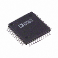
AD73322AST-REEL Analog Devices Inc, AD73322AST-REEL Datasheet - Page 33

AD73322AST-REEL
Manufacturer Part Number
AD73322AST-REEL
Description
IC ANALOG FRONT END DUAL 44-LQFP
Manufacturer
Analog Devices Inc
Datasheet
1.AD73322LARUZ-REEL.pdf
(43 pages)
Specifications of AD73322AST-REEL
Rohs Status
RoHS non-compliant
Number Of Bits
16
Number Of Channels
4
Power (watts)
73mW
Voltage - Supply, Analog
2.7 V ~ 5.5 V
Voltage - Supply, Digital
2.7 V ~ 5.5 V
Package / Case
44-LQFP
Digital Interfacing
The AD73322 is designed to easily interface to most common
DSPs. The SCLK, SDO, SDOFS, SDI and SDIFS must be
connected to the DSP’s Serial Clock, Receive Data, Receive
Data Frame Sync, Transmit Data and Transmit Data Frame
Sync pins respectively. The SE pin may be controlled from a
parallel output pin or flag pin such as FL0-2 on the ADSP-21xx
(or XF on the TMS320C5x) or, where SPORT powerdown is
not required, it can be permanently strapped high using a suit-
able pull-up resistor. The RESET pin may be connected to the
system hardware reset structure or it may also be controlled
using a dedicated control line. In the event of tying it to the
global system reset, it is advisable to operate the device in mixed
mode, which allows a software reset, otherwise there is no
convenient way of resetting the device. Figures 38 and 39
show typical connections to an ADSP-218x and TMS320C5x
respectively.
Cascade Operation
Where it is required to configure a cascade of up to eight codecs
(4 AD73322 dual codecs), it is necessary to ensure that the
timing of the SE and RESET signals is synchronized at each
device in the cascade. A simple D type flip flop is sufficient to
sync each signal to the master clock MCLK, as in Figure 40.
REV. B
Figure 39. AD73322 Connected to TMS320C5x
Figure 38. AD73322 Connected to ADSP-218x
ADSP-218x
TMS320C5x
DSP
DSP
TFS
DT
SCLK
DR
RFS
FL0
FL1
FSX
DT
CLKX
CLKR
DR
FSR
XF
SDOFS
RESET
SDOFS
RESET
SDIFS
SDIFS
SCLK
SDO
SCLK
SDO
SDI
SE
SDI
SE
AD73322
AD73322
CODEC
CODEC
–33–
Connection of a cascade of devices to a DSP, as shown in Fig-
ure 41, is no more complicated than connecting a single device.
Instead of connecting the SDO and SDOFS to the DSP’s Rx
port, these are now daisy-chained to the SDI and SDIFS of the
next device in the cascade. The SDO and SDOFS of the final
device in the cascade are connected to the DSP’s Rx port to
complete the cascade. SE and RESET on all devices are fed
from the signals that were synchronized with the MCLK using
the circuit as described above. The SCLK from only one device
need be connected to the DSP’s SCLK input(s) as all devices
will be running at the same SCLK frequency and phase.
FL0
Figure 40. SE and RESET Sync Circuit for Cascaded
Operation
ADSP-218x
Figure 41. Connection of Two AD73322s Cascaded to
ADSP-218x
DSP
DSP CONTROL
TO SE
DSP CONTROL
TO RESET
MCLK
MCLK
FL1
D1
D2
TFS
DT
SCLK
DR
RFS
74HC74
CLK
CLK
D
D
74HC74
74HC74
1/2
1/2
Q1
Q2
Q
Q
SDOFS
SDOFS
SE SIGNAL SYNCHRONIZED
TO MCLK
RESET SIGNAL SYNCHRONIZED
TO MCLK
SCLK
SDIFS
SCLK
SDIFS
SDO
SDO
SDI
SDI
AD73322
AD73322
CODEC
CODEC
DEVICE 1
DEVICE 2
AD73322
MCLK
MCLK
SE
RESET
SE
RESET


