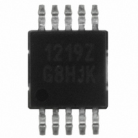
ISL1219IUZ Intersil, ISL1219IUZ Datasheet - Page 5

ISL1219IUZ
Manufacturer Part Number
ISL1219IUZ
Description
IC RTC LP BATT BACK SRAM 10MSOP
Manufacturer
Intersil
Type
Clock/Calendar/NVSRAMr
Specifications of ISL1219IUZ
Memory Size
2B
Time Format
HH:MM:SS (12/24 hr)
Date Format
YY-MM-DD-dd
Interface
I²C, 2-Wire Serial
Voltage - Supply
2.7 V ~ 5.5 V
Operating Temperature
-40°C ~ 85°C
Mounting Type
Surface Mount
Package / Case
10-MSOP, Micro10™, 10-uMAX, 10-uSOP
Clock Format
HH
Clock Ic Type
RTC
Interface Type
I2C, Serial
Memory Configuration
2 X 8
Supply Voltage Range
2.7V To 5.5V
Digital Ic Case Style
MSOP
Rohs Compliant
Yes
Lead Free Status / RoHS Status
Lead free / RoHS Compliant
Available stocks
Company
Part Number
Manufacturer
Quantity
Price
Company:
Part Number:
ISL1219IUZ
Manufacturer:
Intersil
Quantity:
490
Company:
Part Number:
ISL1219IUZ
Manufacturer:
Intersil
Quantity:
222
Part Number:
ISL1219IUZ-T
Manufacturer:
INTERSIL
Quantity:
20 000
I
NOTES:
SDA vs. SCL Timing
Symbol Table
2
Rpu
2. IRQ and F
3. LPMODE = 0 (default).
4. In order to ensure proper timekeeping, the V
5. Typical values are for T = 25°C and 3.3V supply voltage.
6. V
7. These are I
8. A write to register 08h should only be done if V
9. Parameters with MIN and/or MAX limits are 100% tested at +25°C, unless otherwise specified. Temperature limits established by characterization
SYMBOL
C Interface Specifications
and are not production tested
WAVEFORM
(OUTPUT TIMING)
SUP
(INPUT TIMING)
= V
SDA and SCL Bus Pull-up Resistor
Off-chip
DD
OUT
2
SDA
C specific parameters and are not directly tested, however they are used during device testing to validate device specification.
SCL
if in V
SDA
and EVDET Inactive.
t
SU:STA
DD
INPUTS
Must be steady
May change
from LOW
to HIGH
May change
from HIGH
to LOW
Don’t Care:
Changes Allowed
N/A
PARAMETER
Mode, V
5
SUP
Test Conditions: V
t
HD:STA
= V
BAT
t
F
OUTPUTS
Will be steady
Will change
from LOW
to HIGH
Will change
from HIGH
to LOW
Changing:
State Not Known
Center Line is
High Impedance
if in V
t
DD SR-
SU:DAT
DD
Maximum is determined by t
and t
For Cb = 400pF, max is about
2~2.5kΩ. For Cb = 40pF, max is
about 15~20kΩ
DD
BAT
> V
specification must be followed.
= +2.7 to +5.5V, Temperature = -40°C to +85°C, unless otherwise specified. (Continued)
F
Mode.
BAT
TEST CONDITIONS
.
t
HIGH
, otherwise the device will be unable to communicate using I
ISL1219
t
LOW
t
HD:DAT
R
(Note 9)
MIN
t
R
1
t
AA
TYP (Note 4)
t
DH
(Note 9)
t
BUF
MAX
2
C.
t
SU:STO
UNITS NOTES
kΩ
July 15, 2010
FN6314.2
7


