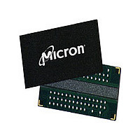
MT47H128M16HG-3:A Micron Technology Inc, MT47H128M16HG-3:A Datasheet - Page 6

MT47H128M16HG-3:A
Manufacturer Part Number
MT47H128M16HG-3:A
Description
Manufacturer
Micron Technology Inc
Type
DDR2 SDRAMr
Datasheet
1.MT47H128M16HG-3A.pdf
(134 pages)
Specifications of MT47H128M16HG-3:A
Organization
128Mx16
Address Bus
17b
Access Time (max)
450ps
Maximum Clock Rate
667MHz
Operating Supply Voltage (typ)
1.8V
Package Type
FBGA
Operating Temp Range
0C to 70C
Operating Supply Voltage (max)
1.9V
Operating Supply Voltage (min)
1.7V
Supply Current
275mA
Pin Count
84
Mounting
Surface Mount
Operating Temperature Classification
Commercial
Lead Free Status / RoHS Status
Compliant
Available stocks
Company
Part Number
Manufacturer
Quantity
Price
Part Number:
MT47H128M16HG-3:A
Manufacturer:
MICRON
Quantity:
20 000
List of Tables
Table 1: Key Timing Parameters ...................................................................................................................... 2
Table 2: Addressing ......................................................................................................................................... 2
Table 3: FBGA 84-Ball – x16 and 60-Ball – x4, x8 Descriptions .......................................................................... 17
Table 4: Input Capacitance ............................................................................................................................ 23
Table 5: Absolute Maximum DC Ratings ........................................................................................................ 24
Table 6: Temperature Limits .......................................................................................................................... 25
Table 7: Thermal Impedance ......................................................................................................................... 26
Table 8: General I
Table 9: I
Table 10: DDR2 I
Table 11: DDR2 I
Table 12: AC Operating Specifications and Conditions .................................................................................... 33
Table 13: Recommended DC Operating Conditions (SSTL_18) ........................................................................ 44
Table 14: ODT DC Electrical Characteristics ................................................................................................... 45
Table 15: Input DC Logic Levels ..................................................................................................................... 46
Table 16: Input AC Logic Levels ..................................................................................................................... 46
Table 17: Differential Input Logic Levels ........................................................................................................ 47
Table 18: Differential AC Output Parameters .................................................................................................. 49
Table 19: Output DC Current Drive ................................................................................................................ 49
Table 20: Output Characteristics .................................................................................................................... 50
Table 21: Full Strength Pull-Down Current (mA) ............................................................................................ 51
Table 22: Full Strength Pull-Up Current (mA) ................................................................................................. 52
Table 23: Reduced Strength Pull-Down Current (mA) ..................................................................................... 53
Table 24: Reduced Strength Pull-Up Current (mA) .......................................................................................... 54
Table 25: Input Clamp Characteristics ........................................................................................................... 55
Table 26: Address and Control Balls ............................................................................................................... 56
Table 27: Clock, Data, Strobe, and Mask Balls ................................................................................................. 56
Table 28: AC Input Test Conditions ................................................................................................................ 57
Table 29: DDR2-400/533 Setup and Hold Time Derating Values (
Table 30: DDR2-667/800/1066 Setup and Hold Time Derating Values (
Table 31: DDR2-400/533
Table 32: DDR2-667/800/1066
Table 33: Single-Ended DQS Slew Rate Derating Values Using
Table 34: Single-Ended DQS Slew Rate Fully Derated (DQS, DQ at V
Table 35: Single-Ended DQS Slew Rate Fully Derated (DQS, DQ at V
Table 36: Single-Ended DQS Slew Rate Fully Derated (DQS, DQ at V
Table 37: Truth Table – DDR2 Commands ..................................................................................................... 71
Table 38: Truth Table – Current State Bank n – Command to Bank n ............................................................... 72
Table 39: Truth Table – Current State Bank n – Command to Bank m .............................................................. 74
Table 40: Minimum Delay with Auto Precharge Enabled ................................................................................. 75
Table 41: Burst Definition .............................................................................................................................. 79
Table 42: READ Using Concurrent Auto Precharge ......................................................................................... 99
Table 43: WRITE Using Concurrent Auto Precharge ....................................................................................... 105
Table 44: Truth Table – CKE ......................................................................................................................... 120
PDF: 09005aef824f87b6
2gbddr2.pdf – Rev. F 12/10 EN
DD7
Timing Patterns (8-Bank Interleave READ Operation) ................................................................. 28
DD
DD
DD
Specifications and Conditions (Die Revision A) ................................................................ 29
Specifications and Conditions (Die Revision C) ................................................................ 31
Parameters .................................................................................................................... 27
t
DS,
t
DH Derating Values with Differential Strobe ..................................................... 63
t
DS,
t
DH Derating Values with Differential Strobe ............................................ 64
6
t
DS
t
Micron Technology, Inc. reserves the right to change products or specifications without notice.
IS and
b
and
REF
REF
REF
t
) at DDR2-667 ..................................... 65
) at DDR2-533 ..................................... 66
) at DDR2-400 ..................................... 66
IS and
t
t
DH
IH) ................................................... 59
2Gb: x4, x8, x16 DDR2 SDRAM
b
.................................................. 65
t
IH) .......................................... 60
© 2006 Micron Technology, Inc. All rights reserved.
Features


