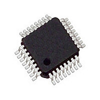
MC34911G5ACR2 Freescale, MC34911G5ACR2 Datasheet - Page 78

MC34911G5ACR2
Manufacturer Part Number
MC34911G5ACR2
Description
Manufacturer
Freescale
Datasheet
1.MC34911G5ACR2.pdf
(92 pages)
Specifications of MC34911G5ACR2
Turn Off Delay Time
10us
Number Of Drivers
2
Operating Temperature (min)
-40C
Lead Free Status / RoHS Status
Compliant
Available stocks
Company
Part Number
Manufacturer
Quantity
Price
Company:
Part Number:
MC34911G5ACR2
Manufacturer:
Freescale Semiconductor
Quantity:
10 000
short to V
LINOC in the LIN Status Register (LINSR) is set.
an Interrupt IRQ will be generated.
Over-temperature Shutdown (LIN Interrupt)
temperature conditions. If an over-temperature condition
occurs, the transmitter will be shut down and the LINOT bit in
the LINSR is set.
generated.
condition is gone and TXD is high.
the transmitter.
RXD Short-circuit Detection (LIN Interrupt)
RXD output pin. In case of a short-circuit condition, either
5.0 V or Ground, the RXSHORT bit in the LINSR is set and
the transmitter is shutdown.
generated.
condition is gone (transition on RXD) and TXD is high.
condition will clear the RXSHORT bit.
TXD Dominant Detection (LIN Interrupt)
stuck-in-dominant (0 V) condition. If a stuck condition occurs
(TXD pin 0V for more than 1 second (typ.), the transmitter is
shut down and the TXDOM bit in the LINSR is set.
generated.
Analog Integrated Circuit Device Data
Freescale Semiconductor
If the LINM bit is set in the Interrupt Mask Register (IMR)
The output low side FET is protected against over-
If the LINM bit is set in the IMR an Interrupt IRQ will be
The transmitter is automatically re-enabled once the
A read of the LINSR with the TXD pin high will re-enable
The LIN transceiver has a short-circuit detection for the
If the LINM bit is set in the IMR an Interrupt IRQ will be
The transmitter is automatically re-enabled once the
A read of the LINSR without the RXD pin short-circuit
The LIN transceiver monitors the TXD input pin to detect
If the bit LINM is set in the IMR an Interrupt IRQ will be
BAT
), the transmitter will not be shut down. The bit
high.
bit TXDOM.
LIN Dominant Voltage Level Selection
LDVS bit in the LIN Control Register (LINCR).
LIN Receiver Operation Only
disables the LIN TXD driver. If a LIN error condition occurs,
this bit is automatically set. If a low-power mode is selected
with this bit set, the LIN wake-up functionality is disabled.
Then in STOP mode, the RXD pin will reflect the state of the
LIN bus.
STOP Mode And Wake-up Feature
physical layer is disabled. If the LIN-PU bit was set in the Stop
mode sequence, the internal pull-up resistor is disconnected
from VSUP and a small current source keeps the LIN pin in
the recessive state. The receiver is still active and able to
detect wake-up events on the LIN bus line.
edge will generate a wake-up interrupt and will be reported in
the Interrupt Source Register (ISR). Also see
SLEEP Mode And Wake-up Feature
physical layer is disabled. If the LIN-PU bit was set in the
Sleep mode sequence, the internal pull-up resistor is
disconnected from V
the LIN pin in recessive state. The receiver must still active to
detect wake-up events on the LIN bus line.
edge will generate a system wake-up (Reset), and will be
reported in the ISR. Also see
The transmitter is automatically re-enabled once TXD is
A read of the LINSR with the TXD pin is high will clear the
The LIN dominant voltage level can be selected by the
While in Normal mode, the activation of the RXONLY bit
During Stop mode operation, the transmitter of the
A dominant level longer than t
During Sleep mode operation, the transmitter of the
A dominant level longer than t
SUP
and a small current source keeps
FUNCTIONAL DEVICE OPERATIONS
Figure
PROPWL
PROPWL
33.
OPERATIONAL MODES
followed by a rising
followed by a rising
Figure
34.
33911
78


