BLF878,112 NXP Semiconductors, BLF878,112 Datasheet
BLF878,112
Specifications of BLF878,112
934061788112
BLF878
BLF878,112
BLF878


Related parts for BLF878,112


BLF878,112 Summary of contents
Page 1
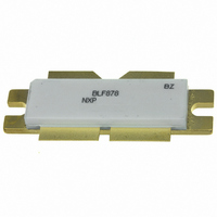
BLF878 UHF power LDMOS transistor Rev. 02 — 15 June 2009 1. Product profile 1.1 General description A 300 W LDMOS RF power transistor for broadcast transmitter applications and industrial applications. The transistor can deliver 300 W broadband over the ...
Page 2
... NXP Semiconductors I Integrated ESD protection I Advanced flange material for optimum thermal behavior and reliability I Excellent ruggedness I High power gain I High efficiency I Designed for broadband operation (470 MHz to 860 MHz) I Excellent reliability I Internal input and output matching for high gain and optimum broadband operation ...
Page 3
... NXP Semiconductors 4. Limiting values Table 4. In accordance with the Absolute Maximum Rating System (IEC 60134). Symbol stg Thermal characteristics Table 5. Symbol R th(j-c) R th(c-h) [1] R th(j-c) [2] R th(c-h) 6. Characteristics Table unless otherwise specified. j Symbol Parameter V (BR)DSS V GS(th) I DSS I DSX I GSS g fs ...
Page 4
... NXP Semiconductors Fig 1. 7. Application information Table unless otherwise specified. case Mode of operation 2-Tone, class AB DVB-T (8k OFDM) [ 1.4 A for total device. Dq [2] Measured [dBc] with delta marker at 4.3 MHz from center frequency. BLF878_2 Product data sheet 350 C oss (pF) 250 150 ...
Page 5
... NXP Semiconductors 7.1 Narrowband RF figures 7.1.1 CW (1) V (2) V Fig 2. BLF878_2 Product data sheet (dB 100 I = 1.4 A; measured in a common source narrowband 860 MHz test circuit power gain and drain efficiency as a function of load power; typical values Rev. 02 — 15 June 2009 BLF878 UHF power LDMOS transistor ...
Page 6
... NXP Semiconductors 7.1.2 2-Tone (dB 100 200 I = 1.4 A; measured in a common source narrowband Dq 860 MHz test circuit Fig 3. 2-Tone power gain and drain efficiency as functions of average load power; typical values BLF878_2 Product data sheet 001aai077 60 IMD3 (1) D (dBc) (2) (%) 300 400 P (W) L(AV) ...
Page 7
... NXP Semiconductors 7.1.3 DVB (2) (dB) ( (1) ( 100 150 I = 1.4 A; measured in a common source narrowband Dq 860 MHz test circuit Fig 5. DVB-T power gain and drain efficiency as functions of average load power; typical values BLF878_2 Product data sheet 001aai079 60 15 IMD3 D (%) (dBc 200 250 0 P (W) ...
Page 8
... NXP Semiconductors 7.2 Broadband RF figures 7.2.1 2-Tone (dB 400 500 600 700 P = 150 1.4 A; measured in a common L(AV) Dq source broadband test circuit as described Fig 7. 2-Tone power gain and drain efficiency as a function of frequency; typical values BLF878_2 Product data sheet 001aai081 80 (2) IMD3 ...
Page 9
... NXP Semiconductors 7.2.2 DVB (dB 400 500 600 700 1.4 A; measured in a common L(AV) Dq source broadband test circuit as described Fig 9. DVB-T power gain and drain efficiency as functions of frequency; typical values 1.4 A; measured in a common source broadband test circuit as described in L(AV) Dq PAR of input signal = 9 0.01 % probability on CCDF. ...
Page 10
... NXP Semiconductors 7.3 Ruggedness in class-AB operation The BLF878 is capable of withstanding a load mismatch corresponding to VSWR = through all phases under the following conditions: V power. 7.4 Impedance information Fig 12. Definition of transistor impedance Table 8. Simulated Z f MHz 300 325 350 375 400 425 450 ...
Page 11
... NXP Semiconductors Table 8. Simulated Z f MHz 925 950 975 1000 7.5 Reliability Years (1) T (2) T (3) T (4) T (5) T (6) T (7) T (8) T (9) T (10) T (11) T Fig 13. BLF878 electromigration (I BLF878_2 Product data sheet Typical push-pull impedance and Z device impedance; impedance info 5.103 + j4.467 5 ...
Page 12
... NXP Semiconductors 8. Test information Table 9. List of components For test circuit, see Figure 14, Figure 15 Component Description B1, B2 semi rigid coax C1, C2 multilayer ceramic chip capacitor C3, C9 multilayer ceramic chip capacitor C4 multilayer ceramic chip capacitor C5, C7, C8 multilayer ceramic chip capacitor C6 multilayer ceramic chip capacitor ...
Page 13
... NXP Semiconductors + V G1(test C30 C28 R1 C26 C24 50 C25 L22 B2 L23 C27 R2 C29 C31 G2(test) See Table 9 for a list of components. Fig 14. Class-AB common-source broadband amplifier; V test voltages L23 L22 95 mm Fig 15. Printed-Circuit Board (PCB) for class-AB common source amplifier BLF878_2 ...
Page 14
... NXP Semiconductors +V G1(test) R7 C28 R3 R5 C30 R1 C26 C25 C27 R2 C31 C29 R8 +V G2(test) See Table 9 for a list of components. Fig 16. Component layout for class-AB common source amplifier BLF878_2 Product data sheet 4 3 C23 C21 C24 C22 C1 C20 12 mm Rev. 02 — 15 June 2009 ...
Page 15
... NXP Semiconductors 9. Package outline Flanged LDMOST ceramic package; 2 mounting holes; 4 leads Dimensions (1) Unit max 5.77 11.81 0.15 31.55 mm nom min 4.80 11.56 0.10 30.94 max 0.227 0.465 0.006 1.242 inches nom min 0.189 0.455 0.004 1.218 Note 1. millimeter dimensions are derived from the original inch dimensions. ...
Page 16
... NXP Semiconductors 10. Abbreviations Table 10. Acronym CW CCDF DVB DVB-T ESD IMD3 LDMOS LDMOST OFDM PAL PAR PEP RF TTF UHF VSWR 11. Revision history Table 11. Revision history Document ID Release date BLF878_2 20090615 • Modifications: Table 4 on page • Table 6 on page • Table 7 on page ...
Page 17
... Right to make changes — NXP Semiconductors reserves the right to make changes to information published in this document, including without limitation specifications and product descriptions, at any time and without notice ...
Page 18
... NXP Semiconductors 14. Contents 1 Product profi 1.1 General description 1.2 Features . . . . . . . . . . . . . . . . . . . . . . . . . . . . . . 1 1.3 Applications . . . . . . . . . . . . . . . . . . . . . . . . . . . 2 2 Pinning information . . . . . . . . . . . . . . . . . . . . . . 2 3 Ordering information . . . . . . . . . . . . . . . . . . . . . 2 4 Limiting values Thermal characteristics Characteristics . . . . . . . . . . . . . . . . . . . . . . . . . . 3 7 Application information 7.1 Narrowband RF figures 7.1 7.1.2 2-Tone 7.1.3 DVB 7.2 Broadband RF figures 7.2.1 2-Tone ...