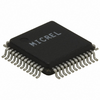
KSZ8001L TR Micrel Inc, KSZ8001L TR Datasheet - Page 7

KSZ8001L TR
Manufacturer Part Number
KSZ8001L TR
Description
10/100 BASE-TX/FX Physical Layer Transceiver With LinkMD Cable Diagnostics, Single 3.3V Supply, 48-LQFP,
Manufacturer
Micrel Inc
Type
Transceiverr
Specifications of KSZ8001L TR
Protocol
MII, RMII, SMII
Voltage - Supply
1.8V, 3.3V
Mounting Type
Surface Mount
Package / Case
48-LQFP
Lead Free Status / RoHS Status
Lead free / RoHS Compliant
For Use With
576-1620 - BOARD EVALUATION FOR KSZ8001L
Number Of Drivers/receivers
-
Lead Free Status / Rohs Status
Compliant
Other names
KSZ8001LTR
KSZ8001LTR
KSZ8001LTR
March 2006
Micrel
Pin Number
17
18
19
20
21
22
23
24
25
26
27
Pin Name
TXD0/
TXD[0]/
TX
TXD1/
TXD[1]/
SYNC
TXD2
TXD3
COL /
RMII_SELE
CT
CRS/
RMII_BTB
GND
VDDIO
INT#/
PHYAD0
LED0/
TEST
LED1 /
SPD100/
noFEF
Type
Ipd
Ipd
Ipd
Ipd
Ipd/O
Ipd/O
Gnd
Pwr
Ipu/O
Ipu/O
Ipu/O
(Note 1)
Pin Function
MII Mode: Transmit Data Input[0] /
RMII Mode: Transmit Data Input[0] /
SMII Mode: Transmit Data and Control
MII Mode: Transmit Data Input[1] /
RMII Mode: Transmit Data Input[1] /
SMII Mode: SYNC
MII Transmit Data Input[2]
MII Transmit Data Input[3]
MII Collision Detect Output
Configuration Mode: The pull-up/pull-down value is latched as RMII select
during reset. See “Strapping Options” section for details.
MII Carrier Sense Output
Configuration Mode: The pull-up/pull-down value is latched as RMII Loop-
back during reset when RMII mode is selected. See “Strapping Options
section” for details.
Ground
3.3V digital VDD
Management Interface (MII) Interrupt Out.
Configuration Mode: Latched as PHYAD[0] during power up / reset. See
“Strapping Options” section for details.
Programmable LED Output 0
Configuration Mode: The external pull down enable test mode and only used
for tfactory test. Active Low. The LED0 pin is also programmable via register
1eh.
LED mode = 00
Link/Act
No Link
Link
Activity
LED mode = 01
Link
No Link
Link
LED mode = 10
10Mbps Link
No Link
Link
Programmable LED Output 1
Configuration Mode: Latched as SPEED (Register 0, bit 13) during power up
/ reset. See “Strapping Options” Section for details. Active Low. The LED1
pin is also programmable via register 1eh.
LED mode = 00
Speed
10BT
100BT
7
Pin State
L
-
L
L
L
H
Pin State
H
Pin State
H
Pin State
H
LED Definition
Off
On
Toggle
LED Definition
Off
On
LED Definition
Off
On
LED Definition
Off
On
Revision 1.03
KSZ8001


