KSZ8001L TR Micrel Inc, KSZ8001L TR Datasheet - Page 10
KSZ8001L TR
Manufacturer Part Number
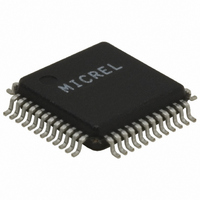
KSZ8001L TR
Description
10/100 BASE-TX/FX Physical Layer Transceiver With LinkMD Cable Diagnostics, Single 3.3V Supply, 48-LQFP,
Manufacturer
Micrel Inc
Type
Transceiverr
Specifications of KSZ8001L TR
Protocol
MII, RMII, SMII
Voltage - Supply
1.8V, 3.3V
Mounting Type
Surface Mount
Package / Case
48-LQFP
Lead Free Status / RoHS Status
Lead free / RoHS Compliant
For Use With
576-1620 - BOARD EVALUATION FOR KSZ8001L
Number Of Drivers/receivers
-
Lead Free Status / Rohs Status
Compliant
Other names
KSZ8001LTR
KSZ8001LTR
KSZ8001LTR


March 2006
Micrel
Strapping Options
Note: Strap-in is latched during power up or reset. In some systems, the MAC RXD pins may drive high at all times causing the
PHY strap-in to be latched high during power up or system reset. In this case, it is recommended to use a strong pull down to GND
via 1kohm resistor on RXDV, RXC, and RXER pins. Otherwise, the PHY may stay in Isolate or loop back modes.
Note 5:
MII Tx Mode: The TXD[3..0] bits are synchronous with TXCLK. When TXEN is asserted, TXD [3..0]
presents valid data from the MAC through the MII. TXD [3..0] has no effect when TXEN is de-asserted.
Note 6:
RMII Tx Mode: The TXD[1..0] bits are synchronous with REF_CLK. For each clock period in which TX_EN
is asserted, two bits of recovered data are recovered by the PHY.
Note 7:
SMII Tx Mode: Transmit data and control information are received in 10 bit segments. In 100MBit mode,
each segment represents a new byte of data. In 10MBit mode, each segment is repeated ten times;
therefore, every ten segments represents a new byte of data. The PHY can sample any one of every 10
segments in 10MBit mode.
Pin Number
6, 5, 4,
3
25
9
10
11
21
22
27
28
29
30
Pin Name
PHYAD[4:1] /
RXD[0:3]
PHYAD0 /
INT#
PCS_LPBK /
RXDV
SMII_SELECT
/ RXC
ISO / RXER
RMII_SELECT
/ COL
RMII_BTB/
CRS
SPD100 /
No FEF /
LED1
DUPLEX/
LED2
NWAYEN/
LED3
PD#
Type
Ipd/O
Ipu/O
Ipd/O
Ipd/O
Ipd/O
Ipd/O
Ipd/O
Ipu/O
Ipu/O
Ipu/O
Ipu
(Note 2)
Description
PHY Address latched at power-up / reset.
The default PHY address is 00001.
Enables PCS_LPBK mode at power-up / reset.
PD (default) = Disable, PU = Enable
Enables SMII mode at power-up / reset.
PD (default) = Disable, PU = Enable
Enables ISOLATE mode at power-up /reset.
PD (default) = Disable, PU = Enable
Enables RMII mode at power-up / reset.
PD (default) = Disable, PU = Enable
Enable RMII_BTB mode at power-up / reset.
PD (default) = Disable, PU = Enable
Latched into Register 0h bit 13 during power-up / reset.
PD = 10Mb/s, PU (default) = 100Mb/s.
If SPD100 is asserted during power-up / reset, this pin also
latched as the Speed Support in register 4h. (If FXEN is
pulled up, the latched value 0 means no Far _End _Fault.)
Latched into Register 0h bit 8 during power-up / reset.
PD = Half Duplex, PU (default) = Full duplex.
If Duplex is pulled up during reset, this pin also latched as the
Duplex support in register 4h.
Nway (auto-=Negotiation) Enable
Latched into Register 0h bit 12 during power-up / reset. PD =
Disable Auto-Negotiation, PU (default) = Enable Auto-
Negotiation
Power Down Enable
PU (default) = Normal operation, PD = Power down mode
10
Revision 1.03
KSZ8001
Related parts for KSZ8001L TR
Image
Part Number
Description
Manufacturer
Datasheet
Request
R

Part Number:
Description:
Manufacturer:
Micrel Inc
Datasheet:
Part Number:
Description:
Manufacturer:
Micrel Inc
Datasheet:
Part Number:
Description:
Manufacturer:
Micrel Inc
Datasheet:
Part Number:
Description:
Manufacturer:
Micrel Inc
Datasheet:
Part Number:
Description:
Manufacturer:
Micrel Inc
Datasheet:
Part Number:
Description:
Manufacturer:
Micrel Inc
Datasheet:
Part Number:
Description:
Manufacturer:
Micrel Inc
Datasheet:
Part Number:
Description:
Manufacturer:
Micrel Inc
Datasheet:
Part Number:
Description:
Manufacturer:
Micrel Inc
Datasheet:
Part Number:
Description:
Manufacturer:
Micrel Inc
Datasheet:
Part Number:
Description:
Manufacturer:
Micrel Inc
Datasheet:
Part Number:
Description:
Manufacturer:
Micrel Inc
Datasheet:
Part Number:
Description:
Manufacturer:
Micrel Inc
Datasheet:
Part Number:
Description:
Manufacturer:
Micrel Inc
Datasheet: