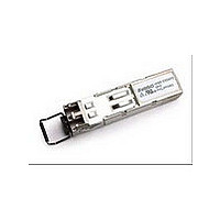
HFBR-57E5APZ Avago Technologies US Inc., HFBR-57E5APZ Datasheet - Page 7

HFBR-57E5APZ
Manufacturer Part Number
HFBR-57E5APZ
Description
MM LC SFP FE DMI ROHS
Manufacturer
Avago Technologies US Inc.
Datasheet
1.HFBR-57E5APZ.pdf
(15 pages)
Specifications of HFBR-57E5APZ
Data Rate
125MBd
Wavelength
1310nm
Applications
Ethernet
Voltage - Supply
3 V ~ 3.6 V
Connector Type
LC Duplex
Mounting Type
SFP
Optical Fiber Type
TX/RX
Optical Rise Time
3/2.2ns
Optical Fall Time
3/2.2ns
Operating Temperature Classification
Industrial
Peak Wavelength
1308/1380nm
Package Type
SFP
Operating Supply Voltage (min)
3V
Operating Supply Voltage (typ)
3.3V
Operating Supply Voltage (max)
3.6V
Operating Temp Range
-40C to 85C
Mounting
Snap Fit To Panel
Pin Count
20
Lead Free Status / RoHS Status
Lead free / RoHS Compliant
Lead Free Status / RoHS Status
Lead free / RoHS Compliant
Available stocks
Company
Part Number
Manufacturer
Quantity
Price
Company:
Part Number:
HFBR-57E5APZ
Manufacturer:
AVAGO
Quantity:
30
Table 7. Transmitter Optical Characteristics
Notes:
1. These optical power values are measured over the specified operating voltage and temperature ranges. The average power value can be converted
2. Duty Cycle Distortion contributed by the transmitter is measured at the 50% threshold of the optical output signal.
3. Characterized with PRBS2
Table 8. Receiver Optical and Electrical Characteristics
Notes:
4. This specification is intended to indicate the performance of the receiver section of the transceiver when Optical Input Power signal characteristics
5. Duty Cycle Distortion contributed by the receiver is measured at the 50% threshold of the electrical output signal.
6. Characterized with PRBS2
7
Parameter
Output Optical Power
62.5/125 Pm NA = 0.275 Fiber
Output Optical Power
50/125 Pm NA = 0.20 Fiber
Extinction Ratio
Central Wavelength
Spectral Width – FWHM
Optical Rise Time (10%-90%)
Optical Fall Time (10%-90%)
Duty Cycle Distortion Contributed
by the Transmitter
Data Dependent Jitter Contributed
by the Transmitter
Random Jitter Contributed by the
Transmitter
Transmitter Disable (High)
Parameter
Optical Input Power
Operating Wavelength
Duty Cycle Distortion Contributed
by the Receiver
Data Dependent Jitter Contributed
by the Receiver
Random Jitter Contributed by the
Receiver
Loss of Signal – De-asserted
Loss of Signal – Asserted
Loss of Signal – Hysteresis
to a peak power value by adding 3 dB.
are present per the following definitions:
x Over the specified operating temperature and voltage ranges
x Bit Error Rate (BER) is better than or equal to 1 x 10
x Transmitter is operating to simulate any cross-talk present between the transmitter and receiver sections of the transceiver.
x Fiber: 62.5/125 Pm, NA = 0.275; or 50/125 Pm, NA = 0.20
7
7
-1 pattern
-1 pattern
Symbol
Symbol
Po
Po
ER
O
'O
t
t
DCD
DDJ
RJ
PO(off )
P
O
DCD
DDJ
RJ
P
P
P
r
f
A
A
c
IN
R
D
– P
D
-10
Min
-20.0
-23.5
10
1270
0.6
0.6
Min
-31.0
1270
-45
0.5
Typ
-17.0
-20.0
1308
147
1.0
1.0
Typ
1.8
Max
Max
-14.0
-14.0
1380
3.0
3.0
0.60
0.60
0.69
-45
-14.0
1380
0.4
1.0
2.14
-32.0
Unit
dBm
dBm
dB
nm
nm
ns
ns
ns
ns
ns
dBm
Unit
dBm
nm
ns
ns
ns
dBm
dBm
dB
Notes
Average power,
Note 1
Average power,
Note 1
Note 2, 3
Note 3
Note 3
Peak-to-peak
Notes
Average power,
Note 4
Note 5, 6
Note 6
Note 6
Peak-to-peak
Average
Average


