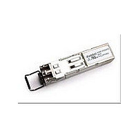
HFBR-57E5APZ Avago Technologies US Inc., HFBR-57E5APZ Datasheet

HFBR-57E5APZ
Specifications of HFBR-57E5APZ
Available stocks
Related parts for HFBR-57E5APZ
HFBR-57E5APZ Summary of contents
Page 1
... FDDI and Fast Ethernet networks with DMI enhancement to the conventional SFP interface defined in SFF-8074i, the HFBR-57E5APZ is compatible to SFF-8472 (digital diagnostic interface for optical trans- ceivers). Using the 2-wire serial interface defined in the SFF-8472 MSA, the HFBR-57E5APZ provides real-time information on temperature, LED bias current, LED average output power and receiver average input power ...
Page 2
... Figure 2. Figures 5 and 7 depict the external configuration and dimensions of the module. Installation The HFBR-57E5APZ can be installed in or removed from any MultiSource Agreement (MSA) compliant Small Form Pluggable port regardless of whether the host equipment is operating or not. The module is simply inserted, electri- cal interface first, under finger pressure ...
Page 3
... Avago has tested the transceiver design for compliance with the requirements listed in Table 1 under normal operating conditions and under a single fault condition. Flammability The HFBR-57E5APZ transceiver housing is made of metal and high strength, heat resistant, chemically resistant and UL-94V-0 flame retardant plastic. Shipping Container ...
Page 4
... SO 4.7k: to 10k: 10PF 50 SI+ 50 SI MOD_DEF2 MOD_DEF1 MOD_DEF0 4.7k to 4.7k to 4.7k to 10k: 10k: 10k VccT HFBR-57E5APZ 10k: TX_GND 0.1PF LED DRIVER TD+ 100: & SAFETY TD 0.1PF CIRCUITRY VccR 0.1PF 0.1PF RD+ AMPLIFIER & RD 0.1PF QUANTIZATION RX_LOS 150: RX_GND CONTROLLER 3 ...
Page 5
Table 2. Pin Description Pin Name Disable 4 MOD-DEF2 5 MOD-DEF1 6 MOD-DEF0 LOS RD- 13 ...
Page 6
Table 3. Absolute Maximum Ratings Stresses in excess of the absolute maximum ratings can cause catastrophic damage to the device. Limits apply to each parameter in isolation, all other parameters having values within the recommended operation conditions. It should not ...
Page 7
Table 7. Transmitter Optical Characteristics Parameter Output Optical Power 62.5/125 0.275 Fiber Output Optical Power 50/125 0.20 Fiber Extinction Ratio Central Wavelength Spectral Width – FWHM Optical Rise Time (10%-90%) Optical Fall Time (10%-90%) ...
Page 8
Table 9. Transceiver diagnostics timing characteristics Parameter Hardware TXDIS Assert Time Hardware TXDIS De-Assert Time Time to Initialize Hardware LOS Assert Time Hardware LOS De-Assert Time Software TX_DISABLE Assert Time Software TX_DISABLE De-Assert Time Software RX_LOS Assert Time Software RX_LOS ...
Page 9
TX, RX Vcc > 2.97V TXDIS TRANSMITTER SIGNAL t_init t_init: TXDIS NEGATED OCCURANCE OF LOSS OPTICAL SIGNAL LOSS OF SIGNAL t_sd_off t_sd_on & t_sd_off Figure 5. Timing diagrams Table 10. Transceiver Digital Diagnostic Monitor (Read Time Sense) Characteristics. Parameter Symbol ...
Page 10
Table 11. EEPROM Serial ID Memory Contents – Address A0h Byte # Decimal Hex ASCII Description 0 03 SFP transceiver connector 100Base-FX compliance ...
Page 11
... Transmitted average optical power (Tx Pwr) is decoded bit unsigned integer in increments of 0.1 PW. 5. Received average optical power (Rx Pwr) is decoded bit unsigned integer in increments of 0.1 PW. 6. Bytes 56-94 are not intended for use with HFBR-57E5APZ, but have been set to default values per SFF-8472. 7. Byte checksum calculated (per SFF-8472) and stored prior to product shipment. ...
Page 12
Table 13. EEPROM Serial ID Memory Contents – Soft Commands (Address A2h, Byte 110). Bit # Status/Control Name Description 7 TX_DISABLE State Digital state of Soft TX_DISABLE 6 Soft TX_DISABLE Read/write bit for changing digital state of TX_DISABLE function 5 ...
Page 13
Table 15. Settings of Alarm and Warning Thresholds Tx power [dBm] High Alarm -10 Low Alarm -23 High Warning -12 Low Warning -22 Tcase Reference Point DEVICE SHOWN WITH DUST CAP AND BAIL WIRE DELATCH 6.25±0.05 [0.246±0.002 Figure ...
Page 14
X Y 16.25 MIN. PITCH B PCB EDGE 5.68 8.58 11.08 16.25 REF . 14.25 2.0 11x 3 3.2 PIN 1 10.93 9.6 0.8 TYP 1.55 ± 0.05 ø0 DETAIL 1 Figure ...
Page 15
PCB [1.64±.02] 15MAX [.59] CAGE ASSEMBLY 12.4REF [.49] 9.8MAX [.39] Figure 8. SFP Assembly Drawing For product information and a complete list of distributors, please go to our web site: Avago, Avago Technologies, and the A logo ...


